Maker Pro
Maker Pro

LED Latch Push Button Help

Status
Not open for further replies.

jakjak55

Aug 25, 2013
10
Joined
Aug 25, 2013
Messages
10
I have a 16mm LED Latching Power Switch. I want to wire it to a battery. It's as simple as that. But! I want the light on the button to only turn on when it is latched.

The switch has 5 prongs, a +, -, no1, nc1, and c1. circ.png

In the above link is my laser weapon design. The button and battery are part of a circuit. The only concern I have is that when the circuit is open (the power button opens all circuits) the button's LED is off too. I only want it to switch on when the button is latched.
 

(*steve*)

¡sǝpodᴉʇuɐ ǝɥʇ ɹɐǝɥd
Moderator
Jan 21, 2010
25,510
Joined
Jan 21, 2010
Messages
25,510
I'm not sure what you mean.

Here is a table showing what the three lights do with the switches in the various positions

Code:
Sw1    Sw2    Red   Green   Flash
 L     off    off     on     off
 L     on     off     on     on
 R     off    on      off    off
 R     on     on      off    off
Now draw me one showing what you want.
 

jakjak55

Aug 25, 2013
10
Joined
Aug 25, 2013
Messages
10
Reply

I want it so when the push button is not latched, nothing is being completed, and the LED is off (not sure if possible with push button design.)

When the SPDT switch is to the left, the green light turns on, indicating that the laser can be fired. (since the flash light case is in parallel with the green light, im hoping it will work)

When the SPDT switch is to the right, the red light is on, indicating that the laser is not armed and cannot be fired.

I originally just wanted to know whether I can wire it so the power switch DOES NOT light up when its not latched. im thinking its designed to light up whether latched or not. at this point, im just trying to confirm that this circuit in general would work.
 

(*steve*)

¡sǝpodᴉʇuɐ ǝɥʇ ɹɐǝɥd
Moderator
Jan 21, 2010
25,510
Joined
Jan 21, 2010
Messages
25,510
I originally just wanted to know whether I can wire it so the power switch DOES NOT light up when its not latched. im thinking its designed to light up whether latched or not. at this point, im just trying to confirm that this circuit in general would work.

It would be just perfect if you could fill in a table as I asked.

I think you mean that you want the green light to only come on if the switch is to the left AND the push button is pressed.

Or is there a third light?
 

jakjak55

Aug 25, 2013
10
Joined
Aug 25, 2013
Messages
10
Laser Rifle Schematics

I need help with the current wiring of my laser rifle. I wired it, but there were problems. The laser could still be triggered even though the power button was off, let alone that the paddle switch was triggered to the right.

Rules for Wiring:
1) When the power button is off, nothing lights up (besides the switch itself, its an LED switch).
2) When the power button is on, either the green led lights up, or the red one does (depending on which side the paddle switch is flipped to.
3) When its to the right, and the red led is on, the laser cannot fire.
4) When its to the left, and the green led is on, the laser can now be fired.
 

jakjak55

Aug 25, 2013
10
Joined
Aug 25, 2013
Messages
10
Here are the attachments.
 

Attachments

  • circ.png
    circ.png
    32.6 KB · Views: 241
  • laserdrawing.jpg
    laserdrawing.jpg
    82.2 KB · Views: 290

(*steve*)

¡sǝpodᴉʇuɐ ǝɥʇ ɹɐǝɥd
Moderator
Jan 21, 2010
25,510
Joined
Jan 21, 2010
Messages
25,510
So let me guess, you think that starting a new thread, and asking your questions again will do you more good than answering the questions you were asked?

At least we now know it's for a "laser rifle"

Now go up to post number 2 and do what I asked you to.

edit: and by the way, your schematic does not describe the same thing that your drawing shows (for one thing there are 2 batteries in the latter)
 

jakjak55

Aug 25, 2013
10
Joined
Aug 25, 2013
Messages
10
Laser Rifle Schematics HELP!

I need help with the current wiring of my laser rifle. I wired it, but there were problems. The laser could still be triggered even though the power button was off, let alone that the paddle switch was triggered to the right.

Rules for Wiring:
1) When the power button is off, nothing lights up (besides the switch itself, its an LED switch).
2) When the power button is on, either the green led lights up, or the red one does (depending on which side the paddle switch is flipped to.
3) When its to the right, and the red led is on, the laser cannot fire.
4) When its to the left, and the green led is on, the laser can now be fired.
 

jakjak55

Aug 25, 2013
10
Joined
Aug 25, 2013
Messages
10
Images for Schematics

These are the attachments that should show you all the information.
 

Attachments

  • circ.png
    circ.png
    32.6 KB · Views: 316
  • laserdrawing.jpg
    laserdrawing.jpg
    82.2 KB · Views: 216

(*steve*)

¡sǝpodᴉʇuɐ ǝɥʇ ɹɐǝɥd
Moderator
Jan 21, 2010
25,510
Joined
Jan 21, 2010
Messages
25,510
And there you go again.

Are you trying to get banned?
 

jakjak55

Aug 25, 2013
10
Joined
Aug 25, 2013
Messages
10
Please disregard everything up until my past two replies. Let's just start again. I apologize for the confusion everybody, Im new to this kind of thing.
 

jakjak55

Aug 25, 2013
10
Joined
Aug 25, 2013
Messages
10
LETS START OVER

I apologize to everyone here. I haven't had my priorities straight until now.

Disregard everything I have asked up until my past two replies. Right now, I wired everything, and just need help with everything working in accordance to those rules I posted. Forget about the power switch problem I had before.

Again, sorry for the confusion.
 

(*steve*)

¡sǝpodᴉʇuɐ ǝɥʇ ɹɐǝɥd
Moderator
Jan 21, 2010
25,510
Joined
Jan 21, 2010
Messages
25,510
Your rules don't make any sense.

I presume the toggle switch is the SPDT switch in your schematic? is the power button the push-button?

Why do you show 2 batteries in the drawing, but one in the totally differently wired schematic?

PLEASE (FOR THE LOVE OF ALL THAT'S GOOD) DO WHAT I ASKED YOU TO DO IN THE SECOND POST OF THIS THREAD.


Is that plain enough?

If the LEDs and the flashlight (laser?) run of different batteries you'll need to tell me that too. (although I see no reason why you need more than one battery.
 

jakjak55

Aug 25, 2013
10
Joined
Aug 25, 2013
Messages
10
I you actually looked at my circuit drawing, it would become extremely APPARENT that the laser module batteries are NOT going to run the RED LED ASSEMBLY circuit when the SPDT switch is flipped to the right. AND if you looked at the circuit drawing, you would already know what kind of batteries those are. it states very clearly what kind they are. If you want the technical term, its "18650 battery" but that's not specific, as there are many kinds of 18650 batteries with different ratings.

CAN I ACTUALLY TALK TO SOMEONE THAT KNOWS SOMETHING ABOUT CIRCUITS PLEASE. I FEEL LIKE IM AT RADIOSHACK.
 

KrisBlueNZ

Sadly passed away in 2015
Nov 28, 2011
8,393
Joined
Nov 28, 2011
Messages
8,393
You won't get very far if you insult Steve. He is the chief contributor to these forums, and very knowledgeable, as you will see if you look at his contributions on other threads.

I suspect he has grown frustrated with you because you have ignored his requests to define your requirements clearly, including his suggestion that you define them using a table that defines your desired behaviour for all possible combinations of switch states.

I am going to give you one chance to be civil and forthcoming.

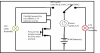
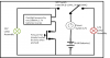
I've had a look at your schematic and your pictorial diagram. This is what I've figured out so far. Please correct anything I've got wrong.

S1. You are using either four AA batteries (4.8V or 6V depending whether they're rechargeable or primary cells) or a 9V PP3-type battery to power the first part of your circuit. I will call this the "first battery".

S2. There is a single-pole changeover toggle switch, and a pushbutton in series with the first battery. When the toggle switch is in one position, pressing the pushbutton will cause a red 12V light bulb to illuminate, but nothing more.

S3. When the toggle switch is in the other position, pressing the pushbutton will cause a green 12V light bulb to illuminate, and this is supposed to enable the laser.

S4. The laser is powered from two separate cells. I will call these the "second battery".

If I understand you properly, your problem is in enabling the laser when the green light is illuminated. The laser uses an independent supply and needs a closed contact to enable it.

If that's the case, a simple answer would be a relay. This is an electromechanical device that is activated by voltage applied to its coil. This voltage would be supplied from the first battery; you would connect the coil across the green light bulb. When the relay is energised, its contacts close, and complete a separate circuit involving the laser and the second battery.

Relays are available with 4.5V, 5V, 6V and 9V coils. They are also available with various current ratings for their contacts. Since you haven't told us how much current the laser draws from its batteries, and it's not clear what voltage the first battery is, I will point you to a number of relays that might fit your requirements, on the Digikey web site. These are in ascending price order.

Coil: 5V, 10 mA. Contact: 0.5A, reed. http://www.digikey.com/product-detail/en/9007-05-00/306-1062-ND/301696
Coil: 5V, 5 mA. Contact: 0.5A, reed. http://www.digikey.com/product-detail/en/9007-05-40/306-1251-ND/710440
Coil: 5V, 30 mA. Contact: 1A. http://www.digikey.com/product-detail/en/G5V-1-DC5/Z773-ND/87831
Coil: 9V, 17 mA. Contact: 1A. http://www.digikey.com/product-detail/en/G5V-1-DC9/Z2539-ND/369041
Coil: 6V, 25 mA. Contact: 1A. http://www.digikey.com/product-detail/en/G5V-1-DC6/Z2538-ND/369040
Coil: 5V, 28 mA. Contact: 2A. http://www.digikey.com/product-detail/en/V23079A2001B301/PB1059-ND/1210002
Coil: 4.5V, 31 mA. Contact: 2A. http://www.digikey.com/product-detail/en/IM02TS/PB1093-ND/1633979
Coil: 6V, 23 mA. Contact: 2A. http://www.digikey.com/product-detail/en/IM04TS/PB1095-ND/1633981
Coil: 9V, 22 mA. Contact: 2A. http://www.digikey.com/product-detail/en/DS2Y-S-DC9V/255-2202-ND/647384
Coil: 9V, 16 mA. Contact: 2A. http://www.digikey.com/product-detail/en/TX2-9V/255-2291-5-ND/649608
Coil: 9V, 6 mA. Contact: 1A. http://www.digikey.com/product-detail/en/TXS2-9V/255-2336-5-ND/650135

The first two items are reed relays. These are physically compact, as well as cheap, but are not designed to switch heavy loads.

The relay coil voltage needs to roughly match the voltage of the first battery.

The relay contact rated current needs to be greater than the amount of current drawn by the laser from the second battery.

The significance of the coil current is not great. A lower current means that less energy is drawn from the first battery while the laser is firing. But the amount of current drawn by the green light bulb may be much greater than the coil current, and, I assume, the laser is not fired for very long periods of time, so the relay coil current may not be an important factor.

If this isn't enough to solve your problem, explain why, and give FULL and CLEAR answers to ALL of the following questions.

Q1. What is the story with the different voltages? Is the first battery 4.8V, 6V, or 9V? Are the bulbs 12V?

Q2. Is the pushbutton (that's in series with the first battery) a momentary type?

Q3. Is the laser supposed to fire immediately and continuously while the pushbutton is pressed, assuming the toggle switch is in the right position? Or is there a separate pushbutton or switch for the laser that needs to be operated in conjunction with the main pushbutton?

Q4. How much current does the laser draw from its batteries?

Q5. How much current do the red and green bulbs draw from the battery you intend to use?

Q6. Why are you using a separate battery for the light bulbs? It would be simpler to use the second battery for both functions.
 
Last edited:

(*steve*)

¡sǝpodᴉʇuɐ ǝɥʇ ɹɐǝɥd
Moderator
Jan 21, 2010
25,510
Joined
Jan 21, 2010
Messages
25,510
Kris, jakjak55 has asked me to delete this thread so he can start again.

I'm just going to lock it in case he wishes to refer back to this thread.
 
Status
Not open for further replies.
Top