Hi all,
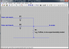
I am writing to see if I can get some help with this project I am doing at the moment. I have a coin payment scale that I need to update by adding a Nayax credit card payment system to it. After a few days of work, the Director from Nayax and I managed to successfully connect it, take payment and release the scale timer. The problem I have is that there is some sort of conflict somewhere because the credit card system won't work if the coin mech is connected as well at the same time. The coin mech and credit card payment work on a pulse system which is sent to the scale motherboard telling it to release the timer. Three wires go from the coin mech to the motherboard: 12v power, pulse and ground. I connected the same wires from the Nayax credit card system which works only if the coin mech is not connected. When both are connected, Nayax system will take payment but does not send pulse to the scale to open the timer. I have tried a diode on the pulse cable from coin mech but same result.
I don't have an electronics background and I am learning on the way so please be kind.")
Thanks
Daniel
I am writing to see if I can get some help with this project I am doing at the moment. I have a coin payment scale that I need to update by adding a Nayax credit card payment system to it. After a few days of work, the Director from Nayax and I managed to successfully connect it, take payment and release the scale timer. The problem I have is that there is some sort of conflict somewhere because the credit card system won't work if the coin mech is connected as well at the same time. The coin mech and credit card payment work on a pulse system which is sent to the scale motherboard telling it to release the timer. Three wires go from the coin mech to the motherboard: 12v power, pulse and ground. I connected the same wires from the Nayax credit card system which works only if the coin mech is not connected. When both are connected, Nayax system will take payment but does not send pulse to the scale to open the timer. I have tried a diode on the pulse cable from coin mech but same result.
I don't have an electronics background and I am learning on the way so please be kind.
Thanks
Daniel