Maker Pro
Maker Pro

Not sure where to put this question

Tinman265

Aug 2, 2023
9
Joined
Aug 2, 2023
Messages
9
I have a project that uses 12v power and uses ground for arduino inputs. I get random triggers when 12v is given or taken away to the accessories.

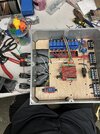
The brain contains 5v, 12v and 110v. The 110v is actuated by a 5v relay controlled by the arduino and powered by the 5v rail that is stepped down from the 12v power supply. There are 4 identical items controlled by the brain. They have 2-12v lights and very small (10mm) cylindrical electromagnets with flyback diodes 1” from the electromagnets. There are 4 wires to each of the 4 items. 12v+, ground, “win” (which is ground returning to the arduino) and a second 12v+ to power the 2 LEDs and the small electromagnet mentioned above. These 4 wires are in a single shielded 4/22 wire that is 6’ long, generally used for security systems, and each of the 4 items has its own 6’ wire from the brain.

The problem: when I supply power to the additional 12v+ for the electromagnet it triggers random “win” inputs. Again, all electromagnets are supplied with flyback diodes.

The questions:
1. Is the likely cause, noise from the 12v+ wire becoming energized inside of the same shielded cable?

If so, can it be solved easily by programming a recheck into the code to confirm the signal? Or am I going to need to separate the signal wires completely from the 12v wires?
 

kellys_eye

Jun 25, 2010
6,514
Joined
Jun 25, 2010
Messages
6,514
Insufficient transient protection on the 5V rail supply to the logics. Use more capacitors on the 5V supply rail (including lower values) and check you have enough decoupling at the supply pins of any discrete logic gates and/or microcontrollers - such decoupling needs to be right at the power pins, not remote from it. You may even require an in-line inductor on the 5V to the Arduino. Potentially include capacitors across the other logic switch inputs too.
 

Tinman265

Aug 2, 2023
9
Joined
Aug 2, 2023
Messages
9
Not sure I follow. The arduino is powered by 12v barrel plug. The 5v rail is only to minimize the draw on the arduino and powers only the 5v relay banks.

As for decoupling, I haven’t seen that. Do you have anywhere that gives good information on techniques to achieve this?
 

bertus

Moderator
Nov 8, 2019
3,382
Joined
Nov 8, 2019
Messages
3,382
Hello

Here is an other page on AAC:

bertus
 

sgodblacktechy

Jul 27, 2023
11
Joined
Jul 27, 2023
Messages
11
Shielding can help, but sometimes it's not enough to completely eliminate interference. For a more robust solution, you might want to consider separating the signal wires completely from the 12v wires. That way, you can keep things cleaner and minimize the chances of interference messing with your arduino inputs.
 

Tinman265

Aug 2, 2023
9
Joined
Aug 2, 2023
Messages
9
Shielding can help, but sometimes it's not enough to completely eliminate interference. For a more robust solution, you might want to consider separating the signal wires completely from the 12v wires. That way, you can keep things cleaner and minimize the chances of interference messing with your arduino inputs.

Currently the 12v and the signal wires are sharing the same shielded casing. I think I’ll run new sets for the signal wires. (Can they run zip tied together if they are each shielded? Probably also rework the configuration of everything in the box to move the signal as far from the voltage as possible. Maybe use the above mentioned techniques to decouple the inputs as well.
Insufficient transient protection on the 5V rail supply to the logics. Use more capacitors on the 5V supply rail (including lower values) and check you have enough decoupling at the supply pins of any discrete logic gates and/or microcontrollers - such decoupling needs to be right at the power pins, not remote from it. You may even require an in-line inductor on the 5V to the Arduino. Potentially include capacitors across the other logic switch inputs too.
given that I am supplying 12v to the arduino is it likely that I am still experiencing fluctuations low enough to trigger an input that Is set to trigger low?

Also… has someone possibly built a shield that handles this issue?

Is there a specific size capacitor that is generally used for this purpose? (Is it a “bigger is better” scenario or a “you better know what size you need and why and do the math to match it perfectly or else” type thing)
 

Hermano

Aug 1, 2023
4
Joined
Aug 1, 2023
Messages
4
Make sure your inputs have RC filters. Something like this:
1691059105624.png
 

danadak

Feb 19, 2021
797
Joined
Feb 19, 2021
Messages
797
Do you have a picture of prototype, and a schematic ?

Datasheets for discrete parts usually have recommendations for power
supply bypassing.

Not all caps equally effective as bypasses for same capacitance :

1691059940004.png


Use your DSO, one shot, to look at supply rails, to see the actual transient
and find the most problematic, use level trigger to discriminate for out of
spec values.....and another examination set it for infinite persistence and
look at supply rails over a few secs to a minute, to see just how large
supply rail noise is.....


Regards, Dana.
 

Tinman265

Aug 2, 2023
9
Joined
Aug 2, 2023
Messages
9
Do you have a picture of prototype, and a schematic ?

Datasheets for discrete parts usually have recommendations for power
supply bypassing.

Not all caps equally effective as bypasses for same capacitance :

View attachment 60164


Use your DSO, one shot, to look at supply rails, to see the actual transient
and find the most problematic, use level trigger to discriminate for out of
spec values.....and another examination set it for infinite persistence and
look at supply rails over a few secs to a minute, to see just how large
supply rail noise is.....


Regards, Dana.
Can all of this be avoided by simply using opto isolater before arduino for all inputs?
 

Tinman265

Aug 2, 2023
9
Joined
Aug 2, 2023
Messages
9
Shielding can help, but sometimes it's not enough to completely eliminate interference. For a more robust solution, you might want to consider separating the signal wires completely from the 12v wires. That way, you can keep things cleaner and minimize the chances of interference messing with your arduino inputs.
Can all of this be avoided by simply using opto isolater before arduino for all inputs?
 

danadak

Feb 19, 2021
797
Joined
Feb 19, 2021
Messages
797
Do you have a DSO you can capture the transient with, such that you can see if
its power rail related, ground bounce, or coupling ?

Schematic of what you are doing, and a pic of prototype and wiring you are working with ....


Regards, Dana
 

Tinman265

Aug 2, 2023
9
Joined
Aug 2, 2023
Messages
9
Do you have a DSO you can capture the transient with, such that you can see if
its power rail related, ground bounce, or coupling ?

Schematic of what you are doing, and a pic of prototype and wiring you are working with ....


Regards, Dana

I don’t have a DSO or a schematic. I can tell you I have flyback diodes on every magnetic device regardless of size all the way down to relays.
531CF885-FC41-4922-869D-DD679675BD13.png
 

Attachments

  • 8BA9CF42-7AA5-4CF9-9CC5-43359759CECB.jpeg
    8BA9CF42-7AA5-4CF9-9CC5-43359759CECB.jpeg
    512.7 KB · Views: 5

danadak

Feb 19, 2021
797
Joined
Feb 19, 2021
Messages
797
Some thoughts :

1) What part number you using for diodes ? Hopefully they are Fast/Ultra Fast types.

2) Is there a ground rail in system where all key grounds are tied to ? It looks like
you have a sort of distributed grounds. Goal, especially in systems like this, is
all grounds meet at a point or a "rail". So that no peripheral current(s) dumped
into ground system "lift" or disturb / ground bounce the V at the digital logic /
processor in system.

Here are methods using Manhatten prototyping that creat great ground rails thru
copper clad :


Manhatten sticky solder pads to use on copper clad boards :


3) Any inputs with high Z pullups ? Hi ZX makes them more susceptible to capacitive
transient coupoling. Solution is to lower the pullups, generally speaking I use a few K,
like 4.7K, for this type of work. They burn more power (not much) but effective when
they are lower. Not driver to them of course has to be able to source the current needed
to achieve low logic level.

4) Bypass caps have vary effectiveness, ESR, depending on technology used in con-
struction and dielectric :

1692203983101.png

OSCON here is Polymer Tantalum. Lower ESR is better.

5) DSO, if you can borrow one they are terrific finding problems. Example you can set
it to trigger on a V level that is too low or too high, single shot, and capture offending
transients. You can look at a power rail with one and look at pk-pk noise on the digital
supply, setting scope on infinite persistence, and give it a couple of minutes or more
to capture a representation of actual PK-PK noise, which a DVM cant properly do.


Regards, Dana.
 
Last edited:

Tinman265

Aug 2, 2023
9
Joined
Aug 2, 2023
Messages
9
thanks. That a lot of info.

1. 1N4001 diodes. It seems to be what everyone uses for mag locks in the escape room industry.

2. Yes the ground rail is the one with green wires going to it. It has 4 individual grounds from the 4 individual chairs that are controlled. That ground provides ground for the 12v items and acts as the source signal to return the “win” condition to the arduino. The other grounds are the barrel plug to arduino. Out to the digital buck converter. Back from the digital buck converter (not sure that’s right to do that way but wasn’t sure what to do with it). Out to the 12v single relay in lower left. And the final one comes in from the 12v power supply.

Having a revelation… should I have a separate “ground” rail for signal grounds to the arduino instead of using using the main ground rail?

Also what is the best way to tie in the 5v relay module? Worried about ground being proper for not only running the relays but for triggering from the arduino.

3. All inputs are internally pulled up on the arduino I believe it’s a 10k onboard resistor that it is routed through. There are only 5 inputs total 4 “wins” and a kill switch in case anyone panics.

4. Way over my head.

5. I don’t know anyone with such equipment. But I can see how that would be very useful.

My next question being, if I simply used an 8 channel optocoupler for my 5 inputs would that not completely isolate the triggers from any noise? Again the problem is that when the 12v relay triggers it randomly triggers one of the 4 inputs from the chairs.

Thanks for all the help. You’ve been very understanding. Many times people are VERY dismissive of a person that doesn’t have a schematic. (I am going to be spending an hour a day learning how to draw schematics but that is scheduled to begin October 1st)
 
Last edited:

danadak

Feb 19, 2021
797
Joined
Feb 19, 2021
Messages
797
4) Basically you want a bypass cap to pass all the noise to ground, to remove it from
the supply rails. ESR (equivalent series resistance) is essentially a measure of its
ability to look, in AC case, noise, like a short to ground for that noise and transients.
ESR is made up of several parasitics, line lead R, internal contact R, lead and construction
L..... So in short lower ESR is better removing AC transients and noise off DC power supply
rails.

My next question being, if I simply used an 8 channel optocoupler for my 5 inputs would that not completely isolate the triggers from any noise? Again the problem is that when the 12v relay triggers it randomly triggers one of the 4 inputs from the chairs.

Un-fortunately a schematic is needed to answer this, where power is flowing and what grounding
looks like. Isolators do help to galvanically isolate pieces of equipment, of there is no common ground
between the source pf signal and destination of signal.

1) 1N4001 s are very slow diodes, so L transients wind up with higher voltage transients before they
turn on and clamp. I would ask the forum for a recommendation here as my knowledge here out of
date. Fast and ultrafast diodes preferred.

My next question being, if I simply used an 8 channel optocoupler for my 5 inputs would that not completely isolate the triggers from any noise? Again the problem is that when the 12v relay triggers it randomly triggers one of the 4 inputs from the chairs.

The Arduino ground wants to be as short as possible wired to the closest box input of the power ground.
The power ground wants to be heavy gauge, prefer stranded wire, to the power source.

Schematic, I know this is a bit of a hill to climb if your not experienced, maybe forum members can comment
on easiest thorough online freebee software to use. We are kind of shooting blanks in the dark on recommendations
without it, allows helpers here to give you the best and thorough advice.

Also what is the best way to tie in the 5v relay module? Worried about ground being proper for not only running the relays but for triggering from the arduino.
Do you have a part number or link to the module, or did I miss that earlier post ?


Regards, Dana.
 
Top