Maker Pro
Maker Pro

Output voltage higher than expected

JimmyShen

Jul 20, 2023
4
Joined
Jul 20, 2023
Messages
4
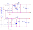
When I solely test this Auxiliary power board(Just use the power supply to provide AUX_DC+, without any loads), the output voltage P_15V and D_6.5V are both a little bit higher. I got 18.8V and 10.1 respectively. Anybody know the reason?

By the way, sometimes when I give the power supply, the 'overload' will be light. But after a while, it will become normal.
1689887205692.png
 

Harald Kapp

Moderator
Moderator
Nov 17, 2011
13,771
Joined
Nov 17, 2011
Messages
13,771
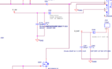
Please supply an enlarged image of this section:
1689912749828.png
Have you tried with some load, e.g. 100 mA on each output? Switch mode power supplies often require a minimum load for the regulation to operate correctly.
 

kellys_eye

Jun 25, 2010
6,514
Joined
Jun 25, 2010
Messages
6,514
Switch mode power supplies often require a minimum load for the regulation to operate correctly.
That was my first thought but since the output looks to be via shunt regulation there's no real way the voltage could exceed what the circuit is designed to deliver.

I suspect it's a case of misplaced ground probe when metering the output.
 

danadak

Feb 19, 2021
797
Joined
Feb 19, 2021
Messages
797
Output is classic series regulated, and its open loop, so Vout = Vz - Vbe.
Principal problem, as an aside, occurs at very high loads where R1 starts starving
the pass transistor for base current and zener drops out of regulation.

Note I cannot tell from schematic if there is fdbk from one of the outputs
due to schematic resolution/readability when magnified. But that would not
change the series regulator output behavior.

1689939924072.png


Note I did not use your part numbers, but general principles apply.

One can envision that as load drops Vbe drops due to base current drop, so
output rises to Vz (its tolerance matters) in the limit.


Regards, Dana.
 
Last edited:

JimmyShen

Jul 20, 2023
4
Joined
Jul 20, 2023
Messages
4
Please supply an enlarged image of this section:
View attachment 59934
Have you tried with some load, e.g. 100 mA on each output? Switch mode power supplies often require a minimum load for the regulation to operate correctly.
1689947327709.png
It works as a regulator and the value for these two outputs is correct. Comparing these two outputs with the remaining two, it seems that the remaining two didn't have a load.
1689947523352.png
 

JimmyShen

Jul 20, 2023
4
Joined
Jul 20, 2023
Messages
4
That was my first thought but since the output looks to be via shunt regulation there's no real way the voltage could exceed what the circuit is designed to deliver.

I suspect it's a case of misplaced ground probe when metering the output.
That two outputs is correct. P_15V and D_6.5V have the problems. I am now also thinking the load. I will try it.
 

crutschow

May 7, 2021
861
Joined
May 7, 2021
Messages
861
the output looks to be via shunt regulation
Not exactly.
It's a common emitter-follower series regulator controlled by a shunt Zener diode reference.
It has no feedback from the output so has poor regulation.
 

danadak

Feb 19, 2021
797
Joined
Feb 19, 2021
Messages
797
As Ib drops so does Vbe and as previously stated Vout = Vz - Vbe, so we have Vout rising :

1689952908663.png


Regards, Dana.
 
Last edited:

kellys_eye

Jun 25, 2010
6,514
Joined
Jun 25, 2010
Messages
6,514
Yes, I meant to type series but somehow didn't realise I'd written shunt! D'oh!
 
Top