Hello
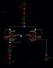
I am designing a PMOS current mirror in 350nm Cadence technology [attached].
Problem: keeping the dimension (W/L ratio) of both the PMOS transistors constant, I should get mirrored current the same as the reference current (according to mirror circuit principle). But I am not getting the same current as reference current. e.g.
-When my reference current is 10uA then the mirror current is 16.6uA with 5V supply voltage (Vdd)
When I change the supply voltage then the mirror current started getting better as e.g.
- reference current 10uA then the mirror current is 13.4uA with 3.3V supply voltage (Vdd).
-reference current 10uA then the mirror current is 10.3uA with 1.8V supply voltage (Vdd).
Dimension of MPO: W/L=10u/0.5u
Dimension of MP1: W/L=10u/0.5u

I would like to know How and Why my mirror current is changing with changing supply voltage (Vdd)?
Thanks
Moderatores note : inverted colors for better readability and posted inline
I am designing a PMOS current mirror in 350nm Cadence technology [attached].
Problem: keeping the dimension (W/L ratio) of both the PMOS transistors constant, I should get mirrored current the same as the reference current (according to mirror circuit principle). But I am not getting the same current as reference current. e.g.
-When my reference current is 10uA then the mirror current is 16.6uA with 5V supply voltage (Vdd)
When I change the supply voltage then the mirror current started getting better as e.g.
- reference current 10uA then the mirror current is 13.4uA with 3.3V supply voltage (Vdd).
-reference current 10uA then the mirror current is 10.3uA with 1.8V supply voltage (Vdd).
Dimension of MPO: W/L=10u/0.5u
Dimension of MP1: W/L=10u/0.5u
I would like to know How and Why my mirror current is changing with changing supply voltage (Vdd)?
Thanks
Moderatores note : inverted colors for better readability and posted inline
Attachments
Last edited by a moderator: