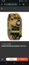
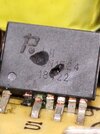
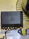
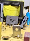
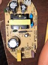
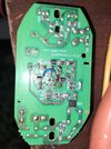
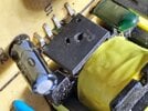
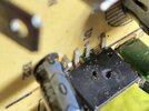
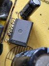
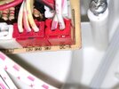
I have this small power supply that output 12v and 38v that only ic is damaged and I do not know its number please help
Attachments
-
 20240226_125803.jpg207 KB · Views: 23
 -
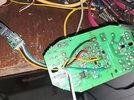
 20240314_145227.jpg344 KB · Views: 21
 -
 20240314_145212.jpg332.9 KB · Views: 20
 -
 20240226_130218.jpg256.9 KB · Views: 20
 -
 20240226_130145.jpg197.5 KB · Views: 22
 -
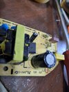
 20240226_130031.jpg243.5 KB · Views: 19
 -
 20240226_125803.jpg207 KB · Views: 19
 -
 20240226_111558.jpg216.6 KB · Views: 19
Last edited by a moderator: