Maker Pro
Maker Pro

Rewiring toroidal transformer

hticheno

Jul 1, 2024
3
Joined
Jul 1, 2024
Messages
3
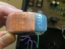
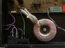
I have a electronic sound processor that was built about 40 years ago in West Germany. Its power supply uses a toroidal transformer to produce 18 volts from a 220 vac mains. Reading the data on the coil it indicates 2 x 110 v primaries and 2 x 18 v secondaries. I want to rewire to use this here with a 110 vac mains. Am I correct: I need to wire the primaries in parallel and the secondaries in series to convert 110 vac to an 18 volt output? Thanks for any guidance you can give. Harold
 

Delta Prime

Jul 29, 2020
2,166
Joined
Jul 29, 2020
Messages
2,166
Welcome to Maker Pro.
The primary windings on these toroidal transformers used in power supplies are where the (utility) mains voltage connects. This is very critical, and things must be correct, or consequences will be fatal and it will hurt the whole time you are dying. Do I make myself clear?
If so I must ask what experience do you have working on main voltages before I can offer you any guidance.
There are industry color codes involved standardized. I don't know about West Germany 40 years ago!
Make model of your sound processor or any information you can provide, perhaps I can research a schematic for your unit that would be the safest way to proceed.
Does any of this look familiar to you...

1719816774200.png

1719816714402.png


1719816537531.png
 
Last edited:

Harald Kapp

Moderator
Moderator
Nov 17, 2011
13,779
Joined
Nov 17, 2011
Messages
13,779
I need to wire the primaries in parallel
yes
the secondaries in series
The wiring of the secondaries remains unchanged.
They are probably not in series (which would result in 2×18 V = 36 V), but uses as positive and negative supply +-18 V with a common center tap as described e.g. here, figures 3 and 4. The symbol for the transformer used in these figures lookes like so:
1719818957283.png
The single coil wit center tap is made of two coils in your case, compare this figure from @Delta Prime 's answer:
1719819052975.png
Connect red and orange (the colors for your transformer will most likely be different) for the center tap. But anyway, as stated before, the secondary side should already be connected correctly. The only change necessary to adapt from 230 V to 115 V is on the primary side.
 

Delta Prime

Jul 29, 2020
2,166
Joined
Jul 29, 2020
Messages
2,166
So much for safety first!
Careful to watch the windings the number of turns the phase windings in this case you will not get away changing from 50 to 60 HZ all this should be accounted for. it is not good engineering practice. 40 years ago
Probably just enamel coated. That cannot be ruled out hence additional information.
 
Last edited:

Minder

Apr 24, 2015
3,480
Joined
Apr 24, 2015
Messages
3,480
If you ever want to confirm the correct connections for two separate (parallel or series} primaries, connected in parallel.
The simple was to ensure the phasing is to connect one conductor of each winding to each other and feed this connection and ONE of the other open ends with 120vac. if you now measure between the two open ends , it should result in close to zero voltage.
If it measures high voltage, swap any pair and try again, when ~ to zero, they can be connected in parallel.
 

hticheno

Jul 1, 2024
3
Joined
Jul 1, 2024
Messages
3
Thank you all. I have actually worked much more with mains voltages than electronics. I have done the wiring in our house construction to code, wired a 6.2 kW solar power system with twin inverters and rewired numerous power tools. I was just uncertain whether the 18v sides were still additive or not.

My toroidal is made by Bennighoven and to the best of my abilities reading the label, I get for the primaries bn-sw, gn-rt and for the secondaries ge-sw, rt-bl. I'd read these as brown-black, green-red and yellow-black, red-blue. Assuming they are in order I would undo the tie between the brown and red primaries and attach the brown to the green side of the mains in and tie the red to the black side of the mains input. And I should be able to leave the secondaries alone. And will change the fuse in the fuse holder to double its original spec for 220 vac. The transformer is labeled 50-60Hz so I am assuming that will not be an issue in the processor.
Forgive the dust on my thumb; the foam pad beneath the transformer is failing and will be replaced.
Again thank you all for your input.
 

Attachments

  • IMG_2902.JPG
    IMG_2902.JPG
    224.9 KB · Views: 6
  • IMG_2899.JPG
    IMG_2899.JPG
    284.8 KB · Views: 6

Delta Prime

Jul 29, 2020
2,166
Joined
Jul 29, 2020
Messages
2,166
Thank you for your response...
I feel much better now...
Didn't want you to receive the Darwin award!!!
Good luck to you...
 

hticheno

Jul 1, 2024
3
Joined
Jul 1, 2024
Messages
3
I am actually contemplating doing this with a two position 110/220 slide switch which will make it more useful to future owners when it leaves my hands. Will print up a label specifying which fuse to use in each case. Thanks again for all your input. It's appreciated.
 

Harald Kapp

Moderator
Moderator
Nov 17, 2011
13,779
Joined
Nov 17, 2011
Messages
13,779
attach the brown to the green side of the mains in and tie the red to the black side of the mains input.
Right.


When I went to school, lowering the primary to half would result in half secondary voltage.
That is still so.
You missed the point: The transformer has 2 primary windings, each for 110 V. One uses these either in parallel for a 110 mains system or in series for a 220 V mains system. The energy transferred is still the same and so are the secondary voltages. This is an, I dare say, classic scheme.
 

Harald Kapp

Moderator
Moderator
Nov 17, 2011
13,779
Joined
Nov 17, 2011
Messages
13,779
Secondary is now therefore 1/2 of what it was also.
No, it isn't.

Assume the number of primary windings to be N1 for each of the two primary windings.
Assume the number of secondary windings to be N2 for any arbitrary secondary winding.

2 primary windings in series on 220 V:
- total number of primary windings = 2 × N1 (series connection).
- transformer ratio: S/P = N2 / (2 × N1)
- secondary voltage: Vsec = 220 V × S/P = 230 V × N2 / (2 × N1) = 110 V × N2/N1

2 primary windings in parallel on 110 V:
- total number of primary windings = N1 (parallel connection).
- transformer ratio: S/P = N2 / N1
- secondary voltage: Vsec = 110 V × S/P = 110 V × N2/N1

Both calculations lead to the same secondary voltage.
 
Top