DanieSpreeth
- Jun 21, 2023
- 8
- Joined
- Jun 21, 2023
- Messages
- 8
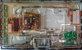
Hey Guys,
Been struggling for a few days since my plasma tv started to refuse to turn on, just the all-known relay clicking sound after power-up...
Through disconnecting power to the other boards one-by-one, I managed to see that connecting the Y-Sus board is what's causing the startup to fail. At first obviously that would be my guess...
Then I checked the output voltages on the power supply to the Y-Sus board and this is what I found:
Vs - should be 205 according to label, when switching TV on, the meter reads about 230V and then immediately starts dropping down to about 15V or less like a capacitor discharging.
Va - should be 55, same happens as above only it starts at 80V then starts dropping.
All other voltages (12V, 5V, 3.3V) going to other boards seems to be ok.
Keeping in mind I would prefer to fix not replace, what would the next step be? Does the specific behavior of the voltage read-outs remind anyone of a previous issue - Im no expert, please help!?