Maker Pro
Maker Pro

Sharp 173 Photointerrupter

Tomer

Jun 16, 2024
7
Joined
Jun 16, 2024
Messages
7
Hello,
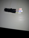
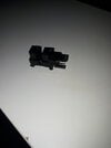
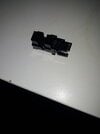
i am trying to use this Photointerrupter sensor:
https://www.sharpsde.com/fileadmin/...hotointerrupter/GP1A173LCS3F_DS_OP14021EN.pdf

Sharp 173
but i am getting always high on the Vout, i try on 5V and also on 3.3V
and i try also to change beetween the VCC and the GND.
but keep getting always high on the Vout.
according to the datasheet the Vout should be normaly low, anwhen the is blocking it should be high.
what am i missing here ?

best regards.
 

Attachments

  • Photointerrupter.png
    Photointerrupter.png
    1.3 MB · Views: 1
  • 20240616_211745.jpg
    20240616_211745.jpg
    65.3 KB · Views: 1
  • 20240616_211654.jpg
    20240616_211654.jpg
    89.9 KB · Views: 1

bertus

Moderator
Nov 8, 2019
3,382
Joined
Nov 8, 2019
Messages
3,382
Hello,

The interuptor has an open collector output.
It will need a resistor between out and vcc to show a signal.
Try an 1K resistor and see what happens.

Bertus
 

Tomer

Jun 16, 2024
7
Joined
Jun 16, 2024
Messages
7
Hello,

The interuptor has an open collector output.
It will need a resistor between out and vcc to show a signal.
Try an 1K resistor and see what happens.

Bertus
Thank you sir,
the resistor between VCC and Vout solve it out,
and also the pins are according to this datasheet:
https://www.mouser.com/datasheet/2/365/gp1s173lcs2f_e-594313.pdf(The Vout on left)
how should i figure out that should be a resistor between the VCC and Vout, Does it mention on the datasheet ?
best regards !!
 

bertus

Moderator
Nov 8, 2019
3,382
Joined
Nov 8, 2019
Messages
3,382
Hello,

In the datasheet there are tests done with resistors of 4.7 and 10K.
With the 1K i mentioned the current will stay below the maximum allowed of 8 mA.

Bertus
 

Tomer

Jun 16, 2024
7
Joined
Jun 16, 2024
Messages
7
Hello,

In the datasheet there are tests done with resistors of 4.7 and 10K.
With the 1K i mentioned the current will stay below the maximum allowed of 8 mA.

Bertus
got it,
thank you !!!
 

Bluejets

Oct 5, 2014
7,057
Joined
Oct 5, 2014
Messages
7,057
Be aware there are PNP as well as NPN open collector in the Sharp range.
 

hevans1944

Hop - AC8NS
Jun 21, 2012
4,891
Joined
Jun 21, 2012
Messages
4,891
how should i figure out that should be a resistor between the VCC and Vout, Does it mention on the datasheet ?
This is just something you have to learn and know about: open-collector vs totem-pole digital outputs. The advantage of open-collector outputs is two or more outputs can be paralleled so that the output will be high if ALL the outputs are high, or conversely, the output will be low if ANY of the outputs are low. A disadvantage of open-collector outputs is limited drive capability when the output is high, and possibly slower response to low-to-high transitions (compared to totem-pole outputs) because stray capacitance to logic common, along with the resistance value of the pull-up resistor, forms an RC low-pass filter that slows down low-to-high transitions.

Note that the data sheet uses a small-valued resistor when measuring rise and fall times, and a fairly narrow pulse, slowly repeated, to avoid excessive current in the photo-transistor. It the output will be low for significant periods of time (photo-transistor is conducting), make sure that this steady-state condition does not result in excessive collector current, yet is high enough to saturate the transistor. For a five-volt supply, one thousand ohms (as @bertus suggested) is usually a good starting value yielding about five milliamperes of collector current when the output is low.
 

Tomer

Jun 16, 2024
7
Joined
Jun 16, 2024
Messages
7
This is just something you have to learn and know about: open-collector vs totem-pole digital outputs. The advantage of open-collector outputs is two or more outputs can be paralleled so that the output will be high if ALL the outputs are high, or conversely, the output will be low if ANY of the outputs are low. A disadvantage of open-collector outputs is limited drive capability when the output is high, and possibly slower response to low-to-high transitions (compared to totem-pole outputs) because stray capacitance to logic common, along with the resistance value of the pull-up resistor, forms an RC low-pass filter that slows down low-to-high transitions.

Note that the data sheet uses a small-valued resistor when measuring rise and fall times, and a fairly narrow pulse, slowly repeated, to avoid excessive current in the photo-transistor. It the output will be low for significant periods of time (photo-transistor is conducting), make sure that this steady-state condition does not result in excessive collector current, yet is high enough to saturate the transistor. For a five-volt supply, one thousand ohms (as @bertus suggested) is usually a good starting value yielding about five milliamperes of collector current when the output is low.
Thank you sir for the detailed and informed answer.
 
Top