Hi
I am having problems with part b of the question.
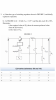
3a) The circuit is a Buck Converter (Step down converter) and that duty cycle is controlled by an OP AMP in comparator mode.
For Part b) I have to started at the voltage divider and trying to work out R2.
which re-arranges to
Vcc being the voltage supply to the OP AMP which is unavailable on the schematic and question info.
I believe R2 can also be given by the
With V_fb being the voltage to the non inverting input of the OP AMP (The current is not supplied for the equation) The current being the current going into R1 at the top of the voltage divider.
Any ideas how I can solve this?
Thanks
I am having problems with part b of the question.
3a) The circuit is a Buck Converter (Step down converter) and that duty cycle is controlled by an OP AMP in comparator mode.
For Part b) I have to started at the voltage divider and trying to work out R2.
which re-arranges to
Vcc being the voltage supply to the OP AMP which is unavailable on the schematic and question info.
I believe R2 can also be given by the
With V_fb being the voltage to the non inverting input of the OP AMP (The current is not supplied for the equation) The current being the current going into R1 at the top of the voltage divider.
Any ideas how I can solve this?
Thanks
Attachments
Last edited by a moderator: