-
Categories
-
Platforms
-
Content
You are using an out of date browser. It may not display this or other websites correctly.
You should upgrade or use an alternative browser.
You should upgrade or use an alternative browser.
Scroll to continue with content
Delta Prime
- Jul 29, 2020
- 2,138
- Joined
- Jul 29, 2020
- Messages
- 2,138
Welcome to Maker Pro
Could you please take a photo of the entire circuit.Thank you
Or perhaps a link or the name of the book page number as well
Thank you in advance. And why is your bridge rectifier crossed out among other components. And is this a class project or homework?
Could you please take a photo of the entire circuit.Thank you
Or perhaps a link or the name of the book page number as well
Thank you in advance. And why is your bridge rectifier crossed out among other components. And is this a class project or homework?
Last edited:
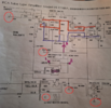
The bridge rectifier is not marked out. The writing was highlighted with a rather dark highlighter. I am just trying to make certain the bias voltage is negative. Do not want to be supplying positive bias to the tubes because I have the vom leads reversed.
Thanks
Thanks
Attachments
Delta Prime
- Jul 29, 2020
- 2,138
- Joined
- Jul 29, 2020
- Messages
- 2,138
Shoot. sorry buddy I'm on a cheapo phone every things all. sideways I can't see nothing somebody will be around to help you.
Delta Prime
- Jul 29, 2020
- 2,138
- Joined
- Jul 29, 2020
- Messages
- 2,138
Wait a minute I got an idea!
You worried about your vom cuz you don't want the needle slamming I take it. Make a model of your vom .
You worried about your vom cuz you don't want the needle slamming I take it. Make a model of your vom .
It is a digital vom with no needle. Just need to know where to connect the ground meter lead so when it indicates a negative voltage is is really negative. I just need to know how to read the voltage across the bias pot correctly. If I have the meter connected incorrectly it could show negative but actually be positive. This circuit has a floating ground so there is no obvious ground connection for testing.
- Joined
- Nov 17, 2011
- Messages
- 13,771
kellys_eye
- Jun 25, 2010
- 6,514
- Joined
- Jun 25, 2010
- Messages
- 6,514
Circuit 'ground' in such cases is inevitably the metal chassis but, in any case, should be taken from the negative of the main supply decoupling (smoothing) capacitor if the structure doesn't have a metal chassis. The 14uF/1kV capacitor in this case.
Please also ensure your meter is rated to read kV - many cheapo meters claim to be but leave a LOT to be desired.
Please also ensure your meter is rated to read kV - many cheapo meters claim to be but leave a LOT to be desired.
73's de Edd
- Aug 21, 2015
- 3,640
- Joined
- Aug 21, 2015
- Messages
- 3,640
HEY ! YOU'SE GUYS . . . . .
Looks like this schematic copying originated or was passed on from . . .
There you see the original 807 tubes receiving their 1st grids biasing by common "grid biasing" wherein they have their first grids returned to ground via a pair of 100K " grid biasing resistors.
The second and third photos are where they have built up a complete add on, of a dedicated - bias circuit and uses a transistor/ zener reference diode combo to establish a bit more reserve than the required - bias voltage, which the pot then trims in exactly..
Fourthly . . . . is your photo with just a basic raw - DC supply.
But on this one . . . . . as compared to the second and third versions . . . . . now do duly take note . . . . of what they forgot at common apexes of 4.7 ufd / 50K / 100ufd / FWB+ items on YOUR and THEIR 4th drawing.
In my rework below, I have steam iron pressed out all of the wrinkles and Clorox bleached out the yellow print and even removed all of the JPEG "crusty" detritus to facilitate your viewing acuity.

Thaaaaaaaaaassit . . . . .
73's de Edd . . . . .
I tried to explain to my 4-year-old g-g-son that it's perfectly normal to accidentally poop your pants, but he's still making fun of ME.
.
Looks like this schematic copying originated or was passed on from . . .
There you see the original 807 tubes receiving their 1st grids biasing by common "grid biasing" wherein they have their first grids returned to ground via a pair of 100K " grid biasing resistors.
The second and third photos are where they have built up a complete add on, of a dedicated - bias circuit and uses a transistor/ zener reference diode combo to establish a bit more reserve than the required - bias voltage, which the pot then trims in exactly..
Fourthly . . . . is your photo with just a basic raw - DC supply.
But on this one . . . . . as compared to the second and third versions . . . . . now do duly take note . . . . of what they forgot at common apexes of 4.7 ufd / 50K / 100ufd / FWB+ items on YOUR and THEIR 4th drawing.
In my rework below, I have steam iron pressed out all of the wrinkles and Clorox bleached out the yellow print and even removed all of the JPEG "crusty" detritus to facilitate your viewing acuity.

Thaaaaaaaaaassit . . . . .
73's de Edd . . . . .
I tried to explain to my 4-year-old g-g-son that it's perfectly normal to accidentally poop your pants, but he's still making fun of ME.
.
Last edited:
Ed, once I added the connection between the +side of the capacitor to chassis ground everything came right into alignment with specs. The old movie theater amp came to life for the first time in 50 years. The sound is unbelievable connected to a pair of Alesis studio reference monitors.HEY ! YOU'SE GUYS . . . . .
Looks like this schematic copying originated or was passed on from . . .
There you see the original 807 tubes receiving their 1st grids biasing by common "grid biasing" wherein they have their first grids returned to ground via a pair of 100K " grid biasing resistors.
The second and third photos are where they have built up a complete add on, of a dedicated - bias circuit and uses a transistor/ zener reference diode combo to establish a bit more reserve than the required - bias voltage, which the pot then trims in exactly..
Fourthly . . . . is your photo with just a basic raw - DC supply.
But on this one . . . . . as compared to the second and third versions . . . . . now do duly take note . . . . of what they forgot at common apexes of 4.7 ufd / 50K / 100ufd / FWB+ items on YOUR and THEIR 4th drawing.
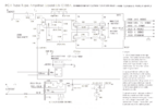
In my rework below, I have steam iron pressed out all of the wrinkles and Clorox bleached out the yellow print and even removed all of the JPEG "crusty" detritus to facilitate your viewing acuity.
View attachment 59715
Thaaaaaaaaaassit . . . . .
73's de Edd . . . . .
I tried to explain to my 4-year-old g-g-son that it's perfectly normal to accidentally poop your pants, but he's still making fun of ME.
.
Attachments
Similar threads
- Replies
- 0
- Views
- 1K
- Replies
- 3
- Views
- 1K
- Replies
- 3
- Views
- 84
- Replies
- 2
- Views
- 239
- Replies
- 17
- Views
- 622


