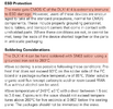
I'm looking to replace a malfunctioning DL1414 vintage red LED display for an Oberheim DMX drum machine from the 80s.
Apparently these display modules are no longer available, but the newer DLR1414 works as a replacement and I've found a dealer who has them.

(image source: MatrixSynth)
Here's my existing (malfunctioning) display modules:


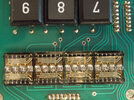
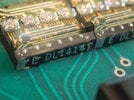
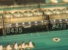
I'll have to replace all four modules because the characters are slightly larger/have different characters from the original (besides I'm sure the other 40 year old display modules are all living on borrowed time and need to be replaced soon anyway).
I have a couple of questions:
1) The replacements I've found have a 'Z' designation (DLR1414 Z) -see photos, but I can't find any information explaining what this means. The Osram DLR1414 datasheet mentions nothing about the 'Z', so it might just be a production code or something. Are these the right type to get?
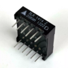 (image source: eBay)
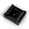
(image source: eBay)
The specs appear to be the same when comparing with the original DL1414 (the datasheet even says "DL1414 T" which is what my existing display modules are labelled as.
2) I read that these are highly sensitive for electrostatic discharge, so I'm worried about handling them when soldering back onto the PCB which is why I'm considering a socket. That would also ensure proper alignment between the four modules and if I'd need t replace them again it would be easy peasy. The pin spacing is 2.54 x 15.24mm (0.1" x 0.6")with a total of 48 pins (2 rows of 24 pins).
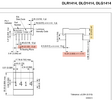
But will I have enough room for a socket? Which solution would add least to the height?
A low profile IC socket? Low profile PCB receptables? Something else worth considering?
A rough and quick measurement tells me I have around 10mm between the surface of the PCB to the drum machine's enclosure. This means I have around 3.9mm additional room for a socket. I suppose I might have to cut the display modules' legs a little shorter.
Apparently these display modules are no longer available, but the newer DLR1414 works as a replacement and I've found a dealer who has them.

(image source: MatrixSynth)
Here's my existing (malfunctioning) display modules:


I'll have to replace all four modules because the characters are slightly larger/have different characters from the original (besides I'm sure the other 40 year old display modules are all living on borrowed time and need to be replaced soon anyway).
I have a couple of questions:
1) The replacements I've found have a 'Z' designation (DLR1414 Z) -see photos, but I can't find any information explaining what this means. The Osram DLR1414 datasheet mentions nothing about the 'Z', so it might just be a production code or something. Are these the right type to get?
 (image source: eBay)
(image source: eBay)
The specs appear to be the same when comparing with the original DL1414 (the datasheet even says "DL1414 T" which is what my existing display modules are labelled as.
2) I read that these are highly sensitive for electrostatic discharge, so I'm worried about handling them when soldering back onto the PCB which is why I'm considering a socket. That would also ensure proper alignment between the four modules and if I'd need t replace them again it would be easy peasy. The pin spacing is 2.54 x 15.24mm (0.1" x 0.6")with a total of 48 pins (2 rows of 24 pins).

But will I have enough room for a socket? Which solution would add least to the height?
A low profile IC socket? Low profile PCB receptables? Something else worth considering?
A rough and quick measurement tells me I have around 10mm between the surface of the PCB to the drum machine's enclosure. This means I have around 3.9mm additional room for a socket. I suppose I might have to cut the display modules' legs a little shorter.
Last edited:
