Mr Random Guy
- May 9, 2016
- 12
- Joined
- May 9, 2016
- Messages
- 12
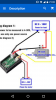
I am quite confused about this dual voltmeter ammeter I want to get off eBay. Please tell me which of these two circuits is right (at least I hope one is right).
So the first idea is that the measuring positive voltage wire and the common negative (between the ammeter and voltmeter) connect to the PSU in parallel with whatever load is connected. My PSU has screw down terminals so I'm thinking solder the two wires onto the base of this so the terminals are still available for loads. The current measuring positive wire would be also connected to the positive of the psu.
The second idea is that the current measure wire would connect to the cathode of the load instead of the positive of the PSU.
I think the second idea is correct because ammeters should always be in series right?
")