Maker Pro
Maker Pro

Wall Charger 120VAC to 5VDC

H2814D

Nov 4, 2017
216
Joined
Nov 4, 2017
Messages
216
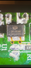
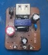
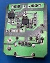
Hi all. My current project involves a relatively simple wall charger/power supply. The circuit board is not complicated at all. So far, I have tested each component on the board and all seem to be working properly. The only component I cannot test, with relative certainty of its proper operation, is the piece with DP1804A on it. A picture of it is attached. It is obviously the "brains" of the entire circuit board. I am unable to find this same component for purchase, but I have found the Datasheet for a DP1804 without the "A" on the end. It says it is a "Quasi-Resonant PSR CC/CV PWM Power Switch."

I am hoping that there is a suitable replacement, if I cannot find the exact same one, and that is why I am here. I have tried to find one by entering the part number and "equivalent" without success. It seems as though it may be a common component and would be used in other wall chargers, or something similar in specs could be found to replace it. Unfortunately, I am not at the level of electronics knowledge to go about finding one. Would any of you know of something compatible, after looking at the Datasheet I have supplied?

Thanks in advance. PS- I realize I could probably buy another charger for less than what it will cost me to fix this one, however, that is not the point. The challenge to fix it is. :)
 

Attachments

  • DP1804A.png
    DP1804A.png
    311.7 KB · Views: 10
  • DP1804-DEVELOPERMICROELECTRONICS.pdf
    1.6 MB · Views: 10
  • Top of PCB.jpg
    Top of PCB.jpg
    19.7 KB · Views: 10
  • Bottom of PCB.jpg
    Bottom of PCB.jpg
    32.7 KB · Views: 11

Delta Prime

Jul 29, 2020
2,166
Joined
Jul 29, 2020
Messages
2,166
 

Attachments

  • DP1804-DEVELOPERMICROELECTRONICS.pdf
    1.6 MB · Views: 0
  • lisuo_1629442246000.pdf
    1.3 MB · Views: 0
  • FAN1080M6X-D.PDF
    414.1 KB · Views: 0
  • journal_jpe_17-6_1732564783.pdf
    1.2 MB · Views: 0
  • primary-wspc-side-wspc-regulation-wspc-controllers.pdf
    1.1 MB · Views: 0

Bluejets

Oct 5, 2014
7,065
Joined
Oct 5, 2014
Messages
7,065
I realize I could probably buy another charger for less than what it will cost me to fix this one, however, that is not the point. The challenge to fix it is. :)
Follow your first instinct......
 

kellys_eye

Jun 25, 2010
6,514
Joined
Jun 25, 2010
Messages
6,514
Seems as if that device might have been a one-off for a particular PSU manufacturer. The 'quasi resonant etc' aspect is common to a lot of such devices however none that my searching found have the built-in high voltage MOSFET to do the switching - they ALL seem to rely on external MOSFET devices which begs the question WHY?

I would venture that the failure rate as a result of the onboard (inbuilt) MOSFET design was the reason the device was removed from production?

Sure, quasi resonant type CONTROL devices can be retrofitted but the challenge to add the required external MOSFET makes the task beyond a reasonable solution.
 

H2814D

Nov 4, 2017
216
Joined
Nov 4, 2017
Messages
216
Obviously English is not your fortae.........
I don't know why you would think that. If I understood your reply to me correctly, you would have preferred I NOT try to fix it and just buy another one.. My response was that my "first instinct" WAS to try and fix it. That was why I was here. The money for a new one was not the concern. The troubleshooting challenge was. That's why I replied with "I am (my first instinct was to fix it and not buy another one)." My English is great. :D
 

H2814D

Nov 4, 2017
216
Joined
Nov 4, 2017
Messages
216
So this is an odd one, but a success, none-the-less. I removed the DP1804A, so I could look underneath it and follow all of the traces to know where they all went. After doing so, and soldering it back to the board, I powered the thing back up and started following the circuit traces, testing voltages as I went. To my surprise, when I got to the DC output voltages at the USB connection, I had my 5VDC back. The charger/power supply is working now.

Note that at the very beginning of my troubleshooting of this thing, I had found the 470uF 10V capacitor (the medium sized one on the board near the USB connection) had a very high ESR but a within tolerance uF reading. I replaced that one, and the other two since I was in there, right away, but still didn't have a working power supply. It was still completely dead. That was why I went ahead and started testing every other component on that board, front and back. Everything else tested good, but like I had mentioned, I wasn't able to verifiably test the DP1804A, thus the reason I came here to ask for help finding a new one or an equivalent. As a side note, I have fixed a whole bunch of these wall chargers and the caps are usually the issue in most of them. That's why this one puzzled me.

So anyway, it is working now. See the pic. And thanks to all for the help you gave me.

PS...I am going to go work on my English. I want it to be my "fortae." ;):p
 

Attachments

  • Now Working.jpg
    Now Working.jpg
    126 KB · Views: 6

73's de Edd

Aug 21, 2015
3,641
Joined
Aug 21, 2015
Messages
3,641
Sir H2814D . . . . .

Looks like you got the unit functioning again, before I had this info available . . . . but I will post the possibilities anyway . . . . .

I marked up that data sheet and circuit board, in relation to your supply's board foil paths and placed it below.
POINTS OF INTEREST . . . .
initially the AC power comes in from the Line input and routes to the FWB mini flat pack and initially had a series surge/fusible resistor in line as shown in the inserted blow-up at the very bottom. Be sure its not blown open.
On the data sheet, there is utilization of a more involved pi filter power supply raw H V DC filtering with inductor, . . . I left it out . . .as, on on yours, its solely the RED E-cap, that is used. ( Circled in ORANGE ).
After that raw DC of ~160VDC is created and stored, it is then routed to the switch mode power transformer, but with a slight circuit variant, where that DC power goes right across via a steering diode into the transformer primary, with the other end of that winding going down to the pins 5-6 collector if the I C's built in power switching transistor, there is also a series R-C snubber across that diode.
That power transistor has a low value SM resistor to hot ground. (PINK Octagon)

ILLUSTRATIONS . . . . .
1704211023064.png

Upon A.C. power plug into the wall, there is a developed main 160 VDC DC that is then initially sent thru a higher value resistor pair *****to drop that voltage on down to a "kick start" voltage level to a medium sized BLACK E-cap (Circled in RED). That initial power burst causes the IC to spit out an initial pulse stream to start the power transformer action . As it gets started, the transformers N aux winding output is fed thru a rectifier diode and into that same E-capacitor as creating the constant main low voltage DC supply for that I.C.
***** On your unit, they opted out of the "creep" distancing provided by a side by side pair of SM resistors and opted for a single L...O...N...G...E...R length SM resistor. ( LIME GREEN triangle marker)

TROUBLESHOOTING . . . . .

Start at the initial AC power input to confirm if the surge/fuse resistor might have blown open.
Next check at the main HOT line supply RED E-cap for time related capacitance decline or developed ESR.
Same is true for the smaller BLACK E-cap nearest to the AC input, as it is being the low voltage RUN supply capacitor for the I.C..
Finally . . . . . up near the DC output connector, there is the sole COLD supply main filter cap.
Relative to the 8 pin I.C., inspect its top side to see if there is any sink hole or cracking of the top of the case at the proximity of
pins 5-6 corner . . . . . . as the POWER switching transistor is built into that corner.

FINALITY . . . . .
Your end problem was likely one or a combination of the three E-caps in the unit. Having gradually tapered off in capacitance until a marginal/intermittent/or/ total no go state.

BTW . . . . .aren't you the party of the first part, twice removed, that was having problems with the lower lighting aspect control of a REE-mote controlled HUNTER(ling) ceiling fanerator ?

Thaaaaaaaaaaaaaaaaassit . . . . .

73's de Edd . . . . . .

On the keyboard of life, ALWAYS keep one finger right beside the escape key.
 
Last edited:

H2814D

Nov 4, 2017
216
Joined
Nov 4, 2017
Messages
216
Hi Edd. Thank you for the detailed explanation and troubleshooting information about how this thing works. There was a picture of the 8 pin IC in my initial post. It was outwardly intact and showed no signs of sink holes or cracking, so with no way for me to check it for sure, my initial thoughts were to just replace it, if I could find another one. I'm actually kind of glad I couldn't find one now, because had I replaced the one I removed with a new one, and if it would have started working afterward like it did when I soldered the original back in, I would have thought that was the problem, when it was not. The puzzling part is why it started working after I resoldered back in the original IC, when I had already replaced each cap with tested good ones.

I had another of these same power supplies that hadn't failed yet, so I unplugged it from the wall and tested it with the tester I have in the picture above. It was outputting just over 3 VDC, and the printed rating on the case says it is supposed to be 5vdc. I opened it up and tested each of the caps. The only one that was bad (high ESR, but again within specs uF) was the one you called "the sole COLD supply main filter cap," a 470uF/10V, by the DC output (USB Connector). On your picture you have it (the foil side of the pcb) circled in yellow. On the second power supply, I only replaced that cap, and was able to get the output voltage up to the rated voltage of 5VDC, so I think that was the only real problem with the first one. But I had replaced that cap right off the bat after opening the first case because of the bad ESR value. When it didn't solve the problem, I did the other two. And then I did what I have mentioned above after that didn't work either, but then it finally did. Anyway, both of them are working correctly now.

As far as me being the guy with the Hunter Fan remote problem. Yes. I am that guy. I was not able to get it to finally work and simply purchased another remote module when one showed up for sale. If you remember, or look back, I had purchased a replacement triac that ended up not testing out as a triac with a component tester. I installed it anyway, thinking my tester may not have the capability of testing it. The tester capability issue was based on another reply to my postings about it. I installed the newly purchased triac and I was still not successful with the repair. In the meantime, I had ordered the same model triac from a different vendor that DID show up as a triac in my tester. I tried the new one and still didn't have success, but I have a feeling the fake triac may have done damage to components on that board that I don't have the skills to diagnose. I do know there was mention of a diac that was supposed to be on that board somewhere too, but I couldn't find it. That remote module is still sitting on my work bench for when I want to get back into it, but now, I don't have it as any kind of priority, because my fan lights are working correctly now, so it is just a reminder of the work I did on it. But yep...It was me. :) Sorry to be so long winded.
 
Top