Build a remote audio oscillator using littleBits mini-PCB modules and view the electrical signals with an oscilloscope.
In this how-to article, learn how to build a remote-operated audio oscillator using littleBits. Once it's built, you can view the electrical signals from the oscillator bit using an oscilloscope and wire a piezo speaker-horn to your remote-operated audio oscillator using a littleBits proto module.
Subcircuit Block Description
For the initial project, there are seven littleBits mini-PCB modules required to build the remote-operated audio oscillator. The seven mini-PCB modules consist of:
- a power bit,
- a remote trigger bit,
- a latch bit,
- an oscillator bit,
- a protoboard,
- an LED bargraph bit,
- a synth speaker bit.
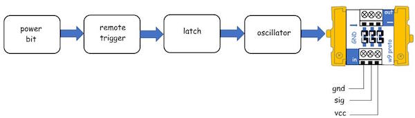
Figure 1 shows a block diagram of the interconnected bits you need to build a remote-operated audio oscillator.
Figure 1. The remote-operated audio oscillator block diagram.
The power bit takes a 9V battery source and regulates it to 5VDC supply. This 5VDC supply powers the connected littleBits PCBs. The remote trigger will provide a 5VDC control signal upon receiving an IR (infrared beam) from an ordinary handheld remote. The latch, which is a digital flip-flop, will toggle the control signal at each IR beam transmission from the handheld remote.
The protoboard allows the IR signal to be measured using either a digital or analog voltmeter or an oscilloscope. With the control signal present, by way of the proto-board, the oscillator will be active. The output signal of the oscillator will control the flash rate of the LED bargraph. Also, you’ll hear the tone from the oscillator through the synth speaker. Now that you have a good operational understanding of the remote-operated audio oscillator, let’s build one!
Construction
The remote-operated audio oscillator construction is quite simple. Build the device using Figure 2 as your construction roadmap.
Figure 2. The construction of the remote-operated audio oscillator.
Attach a 9V battery to the power bit and slide the switch to the “on” position. A tiny red LED will turn on, signifying the remote audio oscillator is powered. Then, activate the device by aiming a handheld remote at the remote trigger bit. You should hear a tone from the synth speaker and should see the LED bargraph flashing. Congratulations, you have successfully built a remote-operated audio oscillator!
To change the sound of the device, you can select between a squarewave or sawtooth waveform using the tiny selector switch on the mini-PCB. Change the tone of your audio oscillator by adjusting the variable resistor (aka potentiometer) on the board. With your device working properly, let's observe some waveforms using an oscilloscope.
Waveform Observations and Measurements
As mentioned briefly, the proto-module will allow you to probe the circuit with a voltmeter or an oscilloscope. You can think of the proto-board as a mini breakout box that allows probing of electrical signals of your littleBits devices and gadgets. Figure 3 shows the method of hacking into the remote-operated audio oscillator with a proto-board to observe the remote trigger control signal using a voltmeter or an oscilloscope.
Figure 3. Hacking into the remote trigger bit using a protoboard.
To observe the remote trigger bit control signal, attach your measuring device (voltmeter or oscilloscope) between gnd and sig terminals of the proto-board. As a reference, my setup on my lab bench is shown next.
Figure 4. The author's setup for observing signals from the remote audio oscillator.
In addition to observing the remote trigger signal, you can observe the audio oscillator’s square and sawtooth waveforms using the following block diagram measurement setup.
Figure 5. Block diagram setup for observing the remote audio oscillator's square and sawtooth waveforms.
Here are pictures illustrating the captured waveforms on an oscilloscope.
Figure 6. The audio oscillator's squarewave signal.
Figure 7. The audio oscillator's sawtooth waveform signal.
Another awesome feature you can check out with this project is to replace the littleBits synth speaker with a piezo speaker-horn.
Figure 8. Replacing the synth speaker with a piezo speaker horn.
The tone of the piezo speaker horn is quite different from the synth speaker bit because the piezo’s natural resonant frequency is stimulated by the audio oscillator’s output signal. You can quickly add your own circuits to the audio oscillator using the protoboard as a mini interfacing breakout module. Try creating our own circuits and wire them to the remote audio oscillator create new methods of controlling the electronic device. Happy making!