Introduction
In the world of DIY electronics, relays play a crucial role in switching electrical devices on and off safely. A relay acts as an electrically operated switch that allows you to control a high-voltage circuit using a low-voltage signal. In this project, we will be using the JS1-24V-F, a 24V electromagnetic relay, to design a smart power switch for controlling various devices. The project will allow you to switch 24V DC appliances (or any 24V device) on and off using a simple control mechanism. Whether you're working on a home automation system, a smart garden project, or a simple power control system, this smart relay switch will be a versatile and effective solution.
This DIY project will involve designing a system where the JS1-24V-F relay is used to control a 24V load based on user input, such as a manual switch, a remote control, or through an automated control system like a microcontroller.
The JS1-24V-F Relay
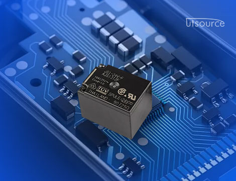
Before we dive into the project details, let’s take a closer look at the JS1-24V-F relay. It’s a 24V relay with the following characteristics:
· Coil Voltage: 24V DC, which is commonly used for industrial and automation systems.
· Contact Rating: Typically, the relay can handle up to 10A of current on its switching contacts, making it suitable for controlling medium to high-power devices.
· Single Pole Double Throw (SPDT): The relay has one input control pin and two output pins, allowing for switching between two states.
· Compact Design: The relay is small and easily integrates into a variety of DIY projects.
· Opto-Isolated (optional): Some versions of the JS1-24V-F relay may have opto-isolation, which is important for protecting the low-voltage control circuit from spikes or noise in the high-voltage circuits.
Project Overview
In this project, we will build a Smart Power Switch using the JS1-24V-F relay to control a 24V DC load (such as a small motor, a light, or a fan). The idea is to use a low-voltage control signal, such as from a manual switch, a microcontroller, or an RF remote control, to activate the relay. When the relay is activated, it will switch the power on or off to the 24V device.
Key Features of the Project:
1. Manual Control: A simple switch will turn the relay on and off, activating or deactivating the 24V load.
2. Remote Control (Optional): The project can be extended to use an RF module or Bluetooth to control the relay remotely.
3. Microcontroller Integration (Optional): For automation, a microcontroller like an Arduino can be used to control the relay based on external sensors, timers, or user input.
4. Load Control: The 24V device can be powered up or down depending on the relay’s state.
Components Required
To build the smart power switch, the following components will be used:
1. JS1-24V-F Relay: This will be the core component used to switch the 24V device on and off.
2. NPN Transistor (e.g., 2N2222): A transistor is used as a switch to drive the relay, as the relay requires more current than most microcontrollers or manual switches can supply.
3. Diode (e.g., 1N4007): A flyback diode is used across the relay coil to protect the transistor from voltage spikes when the relay coil is de-energized.
4. Resistor: A 1kΩ resistor to limit the current to the transistor’s base.
5. Capacitor: A small capacitor (e.g., 0.1μF) across the power supply for noise filtering.
6. Switch: A basic push-button switch for manual control (or an RF remote for remote control).
7. 24V Load: A 24V DC device such as a light, fan, or small motor.
8. External 24V DC Power Supply: To power the load.
9. Breadboard and Jumper Wires: For connecting the components.
10. Optional: An Arduino or other microcontroller (for automation and remote control).
Step 1: Circuit Design
The main task of this project is to wire the JS1-24V-F relay in such a way that it can be controlled using a low-voltage signal. Let’s start by designing the basic relay control circuit:
Relay Control Circuit
Powering the Relay: The JS1-24V-F relay requires 24V DC to operate. This voltage is supplied to the coil terminals of the relay.
Controlling the Relay: A transistor switch (e.g., 2N2222) will be used to control the relay. The base of the transistor is connected to the low-voltage signal (from the switch or microcontroller) through a current-limiting resistor (1kΩ).
Relay Contacts: The NO (Normally Open) contact of the relay will be used to switch the 24V load. When the relay is energized, the NO contact will close, allowing current to flow to the load.
Flyback Diode: A flyback diode (e.g., 1N4007) is connected in parallel with the relay coil, with the cathode (marked side) connected to the 24V supply. This diode protects the transistor from high-voltage spikes generated when the relay coil is turned off.
External Power Supply: The 24V DC power supply will be used to power the relay coil and the connected load. The low-voltage control circuitry will be powered by a separate 5V or 3.3V supply, especially if you're using a microcontroller.
Circuit Connections:
· The collector of the NPN transistor is connected to one end of the relay coil.
· The other end of the relay coil is connected to the 24V supply.
· The emitter of the transistor goes to ground.
· The base of the transistor is connected to the switch or microcontroller through a current-limiting resistor (1kΩ).
· The NO contact of the relay connects to the 24V load.
· The other end of the 24V load is connected to the 24V supply.
Manual Control:
For manual control, a simple push-button switch can be placed between the transistor base and ground. Pressing the button will activate the transistor, energizing the relay and powering the load.
Microcontroller Control:
If using a microcontroller like Arduino, you would connect the base of the transistor to a digital output pin of the Arduino. When the Arduino outputs a HIGH signal, it will turn on the relay, powering the load.
Step 2: Assembling the Circuit
Once you have all the components and have designed the circuit, it’s time to assemble everything:
1. Connect the Relay: Place the JS1-24V-F relay on the breadboard. Connect the relay's coil pins to the power and transistor.
2. Wire the Transistor: Insert the 2N2222 transistor and connect the emitter to ground, the collector to the relay coil, and the base to the switch (or microcontroller).
3. Connect the Diode: Place the flyback diode in parallel with the relay coil to protect the transistor from back-EMF.
4. Wire the Load: Connect the NO (Normally Open) relay contact to the 24V load and the COM to the 24V supply.
5. Power Supply: Connect the 24V DC supply to the relay and the load.
Step 3: Testing the System
Once the circuit is assembled, it's time to test the smart power switch:
1. Manual Control Test: Press the switch to activate the transistor and turn on the relay. The load (24V device) should power on. Press the switch again to turn it off.
2. Microcontroller Control Test (Optional): Upload a simple program to your microcontroller that toggles the output pin connected to the transistor base. Observe how the relay switches the 24V load on and off based on the microcontroller’s signal.
Step 4: Optional Extensions
· Remote Control: Add an RF receiver module and a remote control to trigger the relay wirelessly.
· Automation: Integrate temperature sensors, motion sensors, or timers to automatically turn the relay on and off based on environmental factors.
· Smartphone Control: Use a Bluetooth or Wi-Fi module to control the relay via a smartphone app.
Conclusion
In this DIY project, we’ve successfully built a 24V relay-controlled smart power switch using the JS1-24V-F relay. The project demonstrates how a low-voltage signal can be used to control a high-voltage load, opening up possibilities for home automation, power control, and industrial applications. By extending this basic system, you can create a wide range of intelligent control systems for your DIY projects. Whether you're manually controlling a fan, creating an automated system for your garden, or developing a remote-controlled device, the JS1-24V-F relay offers a flexible and effective solution.
www.utsource.net