Learn how to use the GPIO pins on a Jetson Nano developer kit and how to interface them to different components!
akshay@jetson-nano:~$ sudo cp /opt/nvidia/jetson-gpio/etc/99-gpio.rules /etc/udev/rules.d/
akshay@jetson-nano:~$ sudo udevadm control --reload-rules && sudo udevadm trigger
The Jetson Nano developer kit is ideal for deep learning and AI applications but it does boast of a 40-pin expansion header carrying several GPIO pins that can be used to perform microcontroller level tasks analogous to the Raspberry Pi boards.
This article explains how to use the GPIO pins and interface them to control motors, LEDs, and other electronic components.
GPIO Support on Jetson Nano Developer Kit
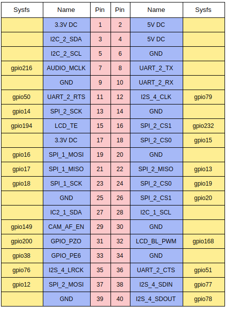
The Jetson Nano Developer Kit has the j41 expansion header with pins similar to the Rasberry Pi. The pinout diagram below shows the different uses of the pins.
Pinout diagram for J41 expansion header on Jetson Nano developer kit
All except the I2C communication pins on the header are directly connected to the Jetson Nano module. The I2C pins are connected to an intermediate level shifter to change voltages from 1.8V on the module to 3.3V on the standard I2C interface. These are pins 3 and 5 (I2C SDA pins) and pins 27 and 28 (I2C SCL pins). Pins 8 and 10 are the UART transmitter (TX) and receiver (Rx) pins, respectively.
The board also provides two 3.3V (pins 1 and 17) and two 5V (pins 2 and 4) power sources. The expansion header has multiple ground pins as well.
The expansion header only has 2 PWM channels directly connected to the hardware PWM controllers. It does not support any software-generated PWM. Unfortunately, the Nano module is not inherently configured to define the connection to the PWM hardware. Thus, to use the PWM hardware, the system PinMux must be configured to provide the functionality to the PWM pins. The documentation provided by Nvidia explains the involved steps but is a fairly complicated task.
Terminal Access to GPIO pins
While the pins on the header provide very low current, it is sufficient enough to light up a small LED.
- Connect an LED to the J41 expansion header with the +ve end to pin 12 and -ve pin to GND.
- Run the following commands in the terminal.
# Climb into the root
akshay@jetson-nano:~$ sudo su
# Set the GPIO
# gpio79 is pin 12 on the Jetson Nano Sysfs
root@jetson-nano:~$ echo 79 > /sys/class/gpio/export
# Set if the pin is an Output or Input pin
root@jetson-nano:~$ echo out > /sys/class/gpio/gpio79/direction
# Set the digital pin 1 (HIGH) or 0 (LOW)
root@jetson-nano:~$ echo 1 > /sys/class/gpio/gpio79/value
root@jetson-nano:~$ echo 0 > /sys/class/gpio/gpio79/value
Interface Using Sample Python Application
The previous example used the terminal to access and modify the digital values on the pins while this application uses a Python interface to the same. The Linux for Tegra package provides the Jetson.GPIO Python library to programmatically talk to the GPIO pins on the board.
Install the Jetson.GPIO library.
akshay@jetson-nano:~$ sudo apt install python3-pip
akshay@jetson-nano:~$ sudo pip3 install Jetson.GPIO
Set up permissions to user and user groups.
akshay@jetson-nano:~$ sudo groupadd -f -r <gpio_group_name>
akshay@jetson-nano:~$ sudo usermod -a -G <gpio_group_name> <user_name>
Add GPIO udev rules to the system and reload the udev rules.
akshay@jetson-nano:~$ sudo cp /opt/nvidia/jetson-gpio/etc/99-gpio.rules /etc/udev/rules.d/
akshay@jetson-nano:~$ sudo udevadm control --reload-rules && sudo udevadm trigger
Note: Users needed to add the udev rules for the GPIO pins from the source to the system udev rules.d directory only if they gave a Jetson Nano running on JetPack 4.2 older (like me!).
To implement the previous application and switch an LED using a Python program, you can use a sample program from the Jetson.GPIO library. This sample toggles the output on Pin 12 of the expansion header digital HIGH and LOW alternately every second.
akshay@jetson-nano:~$ cd /opt/nvidia/jetson-gpio/samples
akshay@jetson-nano:~$ python3 simple_out.py
Note: These samples can be found in the location /usr/share/doc/jetson-gpio-common/samples for JetPack 4.3 and above.
This is the sample code that can be used as the starter code for different projects.
import RPi.GPIO as GPIO
import time

# Pin Definitions
output_pin = 18  # BOARD pin 12, BCM pin 18

def main():
    # Pin Setup:
    # Board pin-numbering scheme
    GPIO.setmode(GPIO.BCM)
    # set pin as an output pin with optional initial state of HIGH
    GPIO.setup(output_pin, GPIO.OUT, initial=GPIO.HIGH)

    print("Starting demo now! Press CTRL+C to exit")
    curr_value = GPIO.HIGH
    try:
        while True:
            time.sleep(1)
            # Toggle the output every second
            print("Outputting {} to pin {}".format(curr_value, output_pin))
            GPIO.output(output_pin, curr_value)
            curr_value ^= GPIO.HIGH
    finally:
        GPIO.cleanup()

if __name__ == '__main__':
    main()
Code Description
The output_pin is defined as 18 for the BCM layout corresponding to physical pin 12 on the J41 expansion header. The expansion header is designed to be compatible with multiple pin numbering styles followed on other platforms like the RPi. These pin modes are configurable via the Jetson.GPIO library API. The available modes are BOARD, BCM, CVM, and TEGRA_SOC.
Inside the main function, the GPIO mode is set to BCM. In the setup line, the output_pin is set as OUTPUT and the initial state is set HIGH. Using the GPIO.output(), the output_pin value is toggled every second. GPIO.cleanup() is used to reset the pin condition to default.
Controlling a DC Motor Using a Python Application
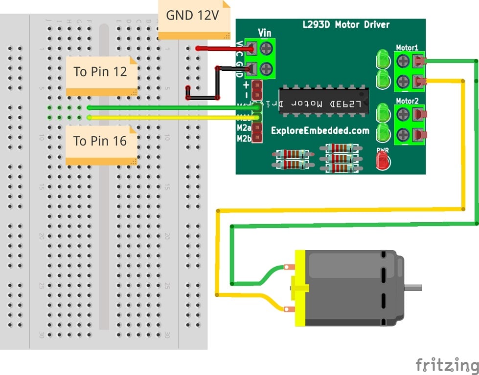
The GPIO pins can be used to simply trigger digital signals to control the motor driver running a DC motor. The L293D H-bridge motor controller is used with a DC motor to control the motor in either direction. The sample code used above is modified and two GPIO pins on the expansion header are connected to the control pins of the H bridge on the L293D motor driver. The schematic is shown here.
Connecting a DC motor to a Jetson nano Expansion Header via the L293D motor driver
import RPi.GPIO as GPIO
import time

# Pin Definitions
motor_pin_a = 18  # BOARD pin 12, BCM pin 18
motor_pin_b = 23  # BOARD pin 16, BCM pin 16

def main():
    # Pin Setup:
    # Board pin-numbering scheme
    GPIO.setmode(GPIO.BCM)
    # Set both pins LOW to keep the motor idle
    # You can keep one of them HIGH and the LOW to start with rotation in one direction
    GPIO.setup(motor_pin_a, GPIO.OUT, initial=GPIO.LOW)
    GPIO.setup(motor_pin_b, GPIO.OUT, initial=GPIO.LOW)

    print("Starting demo now! Press CTRL+C to exit")
    curr_value_pin_a = GPIO.HIGH
    curr_value_pin_B = GPIO.LOW
    try:
        while True:
            time.sleep(5)
            # Toggle the output every second
            print("Outputting {} to pin {} AND {} to pin {}".format(curr_value_pin_a,        motor_pin_a, curr_value_pin_b, motor_pin_b))
            GPIO.output(motor_pin_a, curr_value_pin_a)
            GPIO.output(motor_pin_b, curr_value_pin_b)
            curr_value_pin_a ^= GPIO.HIGH
            curr_value_pin_a ^= GPIO.LOW
    finally:
        GPIO.cleanup()

if __name__ == '__main__':
    main()
Simple changes are made in this example from the previous to add two pins connected to the L293D module. They are alternately toggled HIGH and LOW with a delay of five seconds to change the direction of rotation.
Results and Conclusions
The Jetson Nano developer kit is a powerful AI platform and still supports connections with low-level electronic devices. This makes it suitable to interface AI applications to prototype hardware. Applications could be facial recognition, triggered alarms, or visual servoing using object detection and motion.
Given the complications of configuring the Jetson module before using the hardware PWM pins, the next step is to use the alternate I2C library with a 16 channel 12-bit PWM servo driver PCA 9685 operating on I2C communication.