Before diving into the build, let's define our end-product specifications, the purpose is to show the capability of FRDM-MCXA153, which involves using two FRDM-MC-LVPMSM motor control shields.
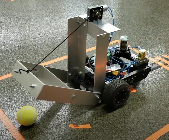
- Purpose: Transport small, low-weight objects within a warehouse.
- Payload Capacity: About 1-2 kg.
- Dimensions: Small form factor (around 30 cm x 20 cm x 15 cm).
- Speed: Moderate speed (0.5 to 1 m/s).
- Navigation: Basic line following with obstacle detection.
- Control System: Differential drive using two DC motors.
- Sensors: Line-following sensors, ultrasonic sensors for obstacle detection, and encoders for wheel feedback.
- Power Supply: Battery-powered, capable of running for at least 2-4 hours.
Here are the mechanical components, that I've compiled based on my experience. I guess, we might require additional things in the end.
Chassis: Lightweight aluminum or acrylic sheet (30 cm x 20 cm).
Wheels: Two rubber or foam wheels for driving and two caster wheels for stability.
Motor Mounts: Suitable mounts to secure the motors to the chassis.
Frame Fasteners: Nuts, bolts, and spacers for assembling the chassis and securing components.
Here is the list for electronic component:
Electronic Components
- MCU Development Board: NXP FRDM-MCXA153 Board
- DC Motors: Two small DC geared motors (e.g., 12V, 100 RPM). Check the material list to find out the manufacturer's part #
- Motor Driver: FRDM-MC-LVPMSM
- Encoders: Embedded in FRDM-MC-LVPMSM module
- Line-Following Sensors: IR sensor TCRT5000 (used also in Arduino)
- Ultrasonic Sensors: HC-SR04 or equivalent for obstacle detection.
- Battery Pack: Rechargeable Li-ion or LiPo battery (7.4V or 12V, 2000-3000 mAh). Check the material list.
- Voltage Regulator: 5V and 3.3V voltage regulators for powering various components.
- Microcontroller Shields: Breadboard or custom PCB for easy wiring and connections.
Miscellaneous
- Cables and Connectors: Jumper wires, connectors, and headers for wiring.
- Tools: Soldering iron, wire cutters, screwdrivers, multimeter and oscilloscope
Choose a lightweight material like aluminum or acrylic. Aluminum provides durability and strength, while acrylic is easier to cut and shape. Design a rectangular base that is compact but has enough space to accommodate all components. You can use software like SolidWorks, AutoCAD, or Fusion 360 to create a 3D model of your AGV, it certainly helps in visualizing.
IMPORTANT THINS TO CONSIDER:
Please note the following, because the efficiency of your AGV depends on the placement of your IR sensor and Ultrasonic sensor.
Motors and Wheels: Place the DC motors towards the rear with wheels directly attached to the motor shafts. Attach the caster wheels to the front for stability.
Sensor Mounting: Position the line-following sensors towards the front and underneath the chassis. Ultrasonic sensors should be mounted at the front and sides for obstacle detection.
Battery and Electronics: Place the battery in the center for balanced weight distribution. Mount the FRDM-MCXA153 and motor driver modules securely on the chassis.
Component Mounting;
Few tips regarding the mounting of the components:
- Motor Mounts: Attach the motors to their respective mounts on the chassis.
- Wheel Attachment: Secure the wheels to the motor shafts.
- Sensor Mounting: Attach the sensors to the chassis using screws or adhesive mounts.
- Electronics Placement: Mount the FRDM-MCXA153, motor driver, and other electronics on the chassis, ensuring easy access to all connections. And also keep in mind that please don't place the board near batteries for safety reasons.
Motor Driver Connections
- MCU to Motor Driver: You need to place/mount the FRDM-MC-LVPMSM on top NXP MCU board. PWM output pins from the FRDM-MCXA153 to the motor driver’s input pins for speed control will be connected then and you will just need to program the drive of the motor in software.
c. Sensor Integration
- Line-Following Sensors: Connect the line-following sensors to the digital input pins of the MCU.
- Ultrasonic Sensors: Connect the ultrasonic sensors’ trigger and echo pins to digital pins on the MCU.
d. Encoder Integration
- Encoder Connections: Two encoders are already present in the FRDM-MC-LVPMSM which will be used in the feedback control loop for speed/position control of the motor.
FINAL STEP: Programming and Control Logic Development
Cooool, if you have already managed to come this far. Now the last step involves programming the MCU
a. Set Up Development Environment
- Install MCUXpresso IDE: Download and install the MCUXpresso IDE from NXP’s website.
- Configure the MCU: Set up the FRDM-MCXA153 board in the IDE and configure the necessary peripherals (PWM, ADC, GPIO, UART).
b. Develop Control Algorithms
Motor Control: Write code to control motor speed and direction using PWM signals.
Line-Following Algorithm: Implement a line-following algorithm using data from the infrared sensors. This could involve simple proportional control or more advanced PID control.
Obstacle Detection: Use the ultrasonic sensors to detect obstacles and modify the AGV’s path accordingly.
Feedback Loop: Implement a feedback loop using encoder data to maintain accurate speed and direction.
c. Test and Debug
Test each module independently (motors, sensors, encoders) to ensure they are working correctly. Integrate all modules and test the AGV’s functionality in a controlled environment. Debug any issues that arise.