Are you eager to dive into 3D-printed electronics but daunted by the high costs of commercial AME printers? Fear not! Today’s project is all about democratizing this technology with a DIY Cartesian conductive pen plotter that brings affordability and accessibility to the forefront.
The vision
The goal is to make 3D-printed electronics approachable and affordable. While industrial AME printers are impressive, they’re also costly. This project allows you to build a capable and cost-effective alternative that puts powerful electronics prototyping tools within reach of anyone with a passion for innovation.
We’re using an FRDM-MCXN947 board with the NXP MXCN947 microcontroller and integrating a camera for control feedback and precise layer alignment. Let’s break it down!
What You’ll Need
Frame and Motion Components:
• 3D-Printed Frame: The entire frame is 3D printed using PLA, which is affordable and easy to work with on an FDM 3D printer. The STL files for the frame parts are based on David Zanetti’s “Arduino mini CNC Plotter”, and can be found at:
• NEMA 17 stepper motors
• 12x M3x10 screws
• A thin steel sheet and magnets (An FDM 3D printer steel plate should work perfect)
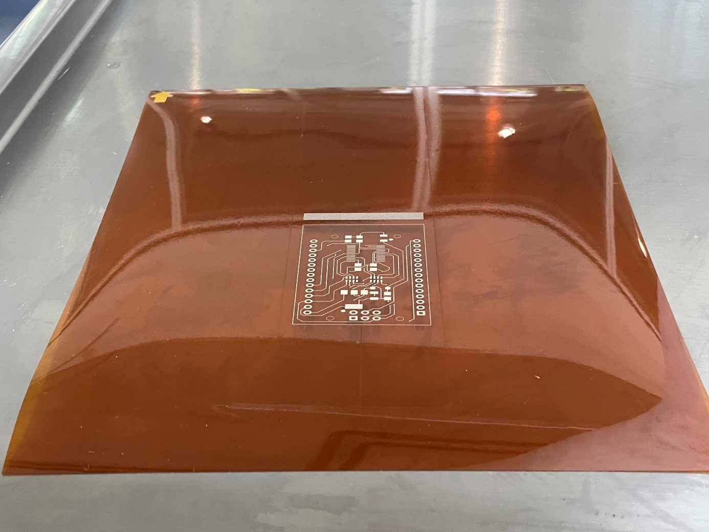
• A 20x20 cm Kapton sheet per printed layer as substrate
• (optional but highly recommended): Endstop switches
Electronics:
• FRDM-MCXN947 Board: This board is Arduino-compatible and features the NXP MXCN947 microcontroller, offering the processing power needed for precise control and vision integration.
• Stepper Motor Drivers: A4988 or DRV8825 drivers. The Arduino CNC shield was used since it plugs nicely into FRDM-MXCN947 board
• Power Supply: 12V or 24V depending on your motors
• Conductive Ink Pen: Circuit Scribe, AgIC, or MG Chemicals Silver Conductive pen.
• Vision System:
• OV7670 Camera Module: For layer alignment and feedback
Software:
• Firmware: Custom firmware compatible with the MXCN947 for plotter control
• GitHub Image Recognition Project: The software leverages an image recognition project from GitHub to provide accurate layer alignment. The project link is here.
• G-code Conversion Tools: Inkscape with a G-code plugin
• G-code Sender: Software to interface with the FRDM-MCXN947
Tools:
• 3D printer (for custom parts like the pen holder and camera mount)
• Basic hand tools (screwdrivers, wrenches, etc.)
Building the 3D-Printed Frame
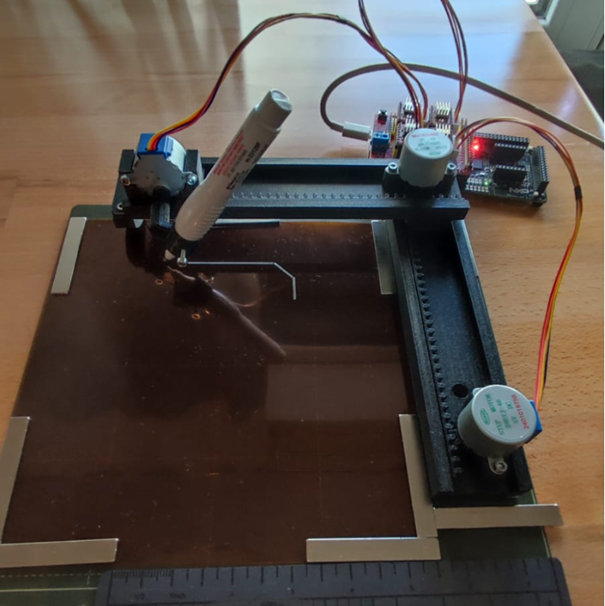
To keep costs low and make this project as accessible as possible, the entire frame is 3D printed using PLA on an inexpensive FDM 3D printer. No mechanical parts are added other than screws. This reduces the precision of the minimum features but broadens the possibility to build the project in any geography.
The design files (STL) for all the frame components come from a Thingiverse project. Simply print the parts and assemble them with M3x10 screws.
to create a sturdy and functional structure. Make sure that your pen fits the provided pen handler. A
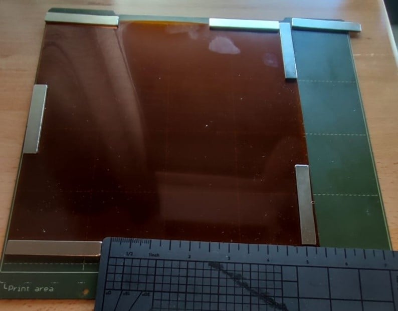
Mounting the Substrate
To hold the substrate to the printing area, simply stick a Kapton sheet to a printer metal plate with several magnets as shown below. The Kapton sheet will serve as our substrate and each one will hold a circuit layer.
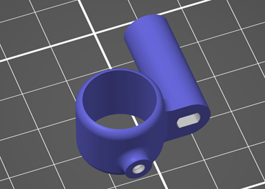
Mounting the Pen and Camera
Create a holder for the conductive ink pen and mount it on the Z-axis. This holder should allow for easy replacement and adjustment. In case your pen doesn’t fit the original pen holder from Thingiverse, which was my case, you can design a new one. I’m providing the modified file I created to handle the 8424R-P pen from MG-Chemicals:
For the vision system, mount the OV7670 camera module above the plotter bed. The camera is required to provide real-time feedback to help align and register additional circuit layers.
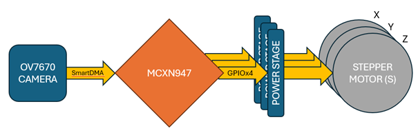
Hardware and Integration
Hardware block diagram is very simple, it only requires the interface over GPIO of the three axis stepper motors. The SmartDMA bus is accessed through J9: Pins 5-23 in the FRDM-MCXN947 board.
First, Connect the stepper motors to the A4988 or DRV8825 drivers, and then to the FRDM-MCXN947 board. In my project, I used inexpensive 28BYJ-48 stepper motors with the Arduino CNC shield, so a small modification in the wiring must be made according to the guide here.
For the camera integration, connect the OV7670 module to the FRDM-MCXN947 board as recommended in this GitHub Project.
Software and Firmware
The software for this project leverages an Arduino project from GitHub for the motion of the CNC. The project can be accessed here. This will give us the ease to control our CNC by G-codes.
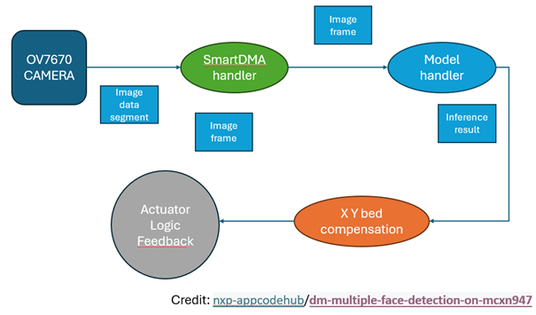
For the vision system, an open-source image recognition project from GitHub is also leveraged, which must be modified for layer alignment in this application. You can find the original project here.
Develop custom firmware for the FRDM-MCXN947 to control the plotter’s movement and integrate the camera’s feedback. This firmware should be capable of interpreting G-code and handling the SmartDMA data from the camera for precise layer alignment.
Calibration and Testing
Calibrate your plotter to ensure accurate movement and layer alignment. This involves setting the steps per millimeter and fine-tuning the Z-axis for precise pen positioning. Universal G-code sender project from GitHub will ease this task. There are several videos on Youtube on how to do that.
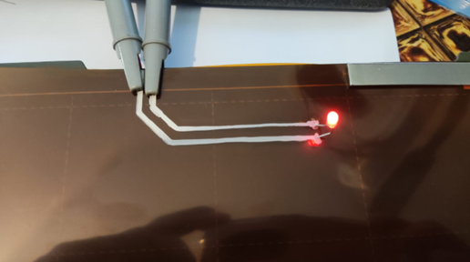
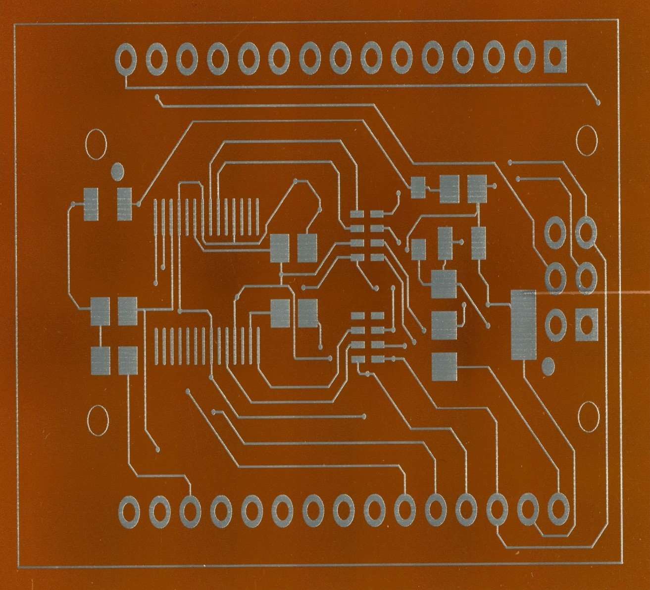
The First Print
Load your conductive ink pen, prepare your substrate, and start your first print. Use the real-time feedback from the camera to ensure each layer aligns perfectly with the previous ones. This setup will enable you to build up complex circuits with high precision.
Applications and Expansion
This plotter is designed to make 3D-printed electronics more accessible. It’s perfect for rapid prototyping, educational demonstrations, and creating interactive projects. As you get comfortable with the basic setup, consider expanding the project by adding more advanced features like automated component placement or integrating additional sensors.
By focusing on affordability and accessibility, this DIY Cartesian pen plotter could be a game-changer in the world of 3D-printed electronics. With the FRDM-MCXN947 board, OV7670 camera, and 3D-printed frame, you’re equipped to create a powerful and precise tool for electronic circuit fabrication. Ready to bring your circuits to life? Dive into this project and start creating!