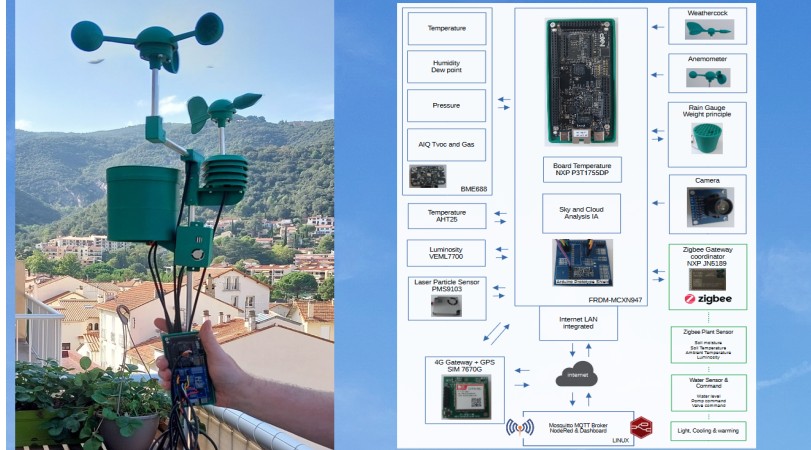
The goal of this project is to create an environmental controller based on the new NXP FRDM-MCXN947 board and to regularly poll the connected or nearby environmental and weather sensors via ZigBee in order to transmit the results to the MQTT server and manage automation. The AI part is used with the camera for a sky status feedback.
Introduction
the goal of this project is to create an environmental controller based on the new NXP Card FRDM-MCXN947.
This device is responsible for regularly polling multiple environmental and weather sensors connected or in the nearby area via ZigBee in order to transmit the results locally or via the Internet to an MQTT server. It can also receive orders from MQTT for actuation of pumps or valves.
This device can use camera and his IA capabilities for analyse the sky and clouds for returning states : clear, cloudy, fog, lightning storms, color, etc...
The project use the Motherboard FRDM-MCXN947, this card is fixed on a support made with a 3D printer in ASA material with DIN Connector for fix it in technical box IP67 or IP68 with Din Rail. The project must uses sensors to use alone or with mechanical parts.
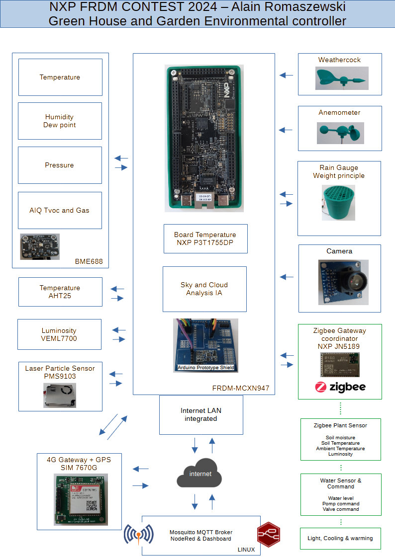
The objectif are to measure and send results to a Mqtt server :
- Wind Direction.
- Wind Speed.
- Rain Fall.
- Temperature.
- Luminosity.
- Humidity.
- Atmospheric Pressure.
- Air quality.
- Tvoc.
- Particle in air.
- Gas.
- Manage Zigbee coordinator to receive distant information about soil moisture, soil temperature, level of water, instant power of solar panels and also to send command for pumps, valves or actuators.
- use IA for image analysis of sky for returning states.
The plenty number of interface with MCXN947 allows to connect all the sensors.
Parts of the project
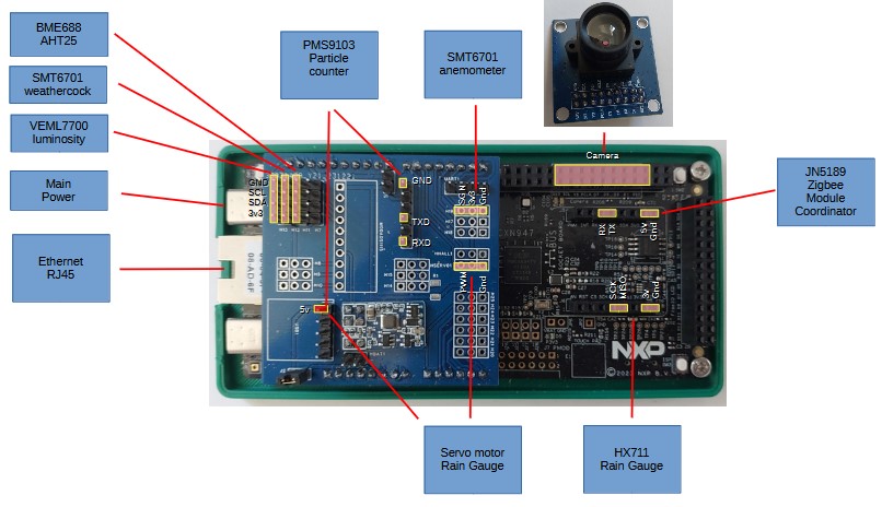
Main Motherboard FRDM-MCXN947
This card is built on MCXN947VDFT processor with 2 cores ARM33 16KBytes of cache, a Neural Processor Unit, a DSP accelerator, 2MBytes of Flash, 512KBytes of RAM, 16Kbytes of RAM with Vbat, 10 Flexcomms configurable as SPI, I2C,UART ; 5 counters of 32bits with capture or compare value possibilities, an ethernet interface 10/100Mbits, a can interface, an usb and many others rich capabilities.
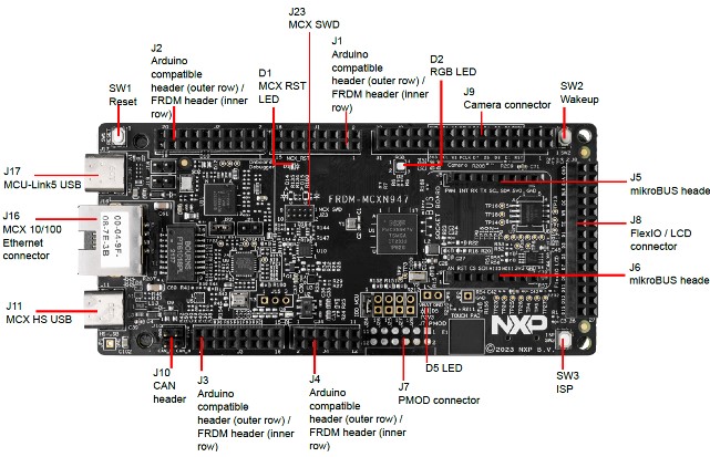
This card have many connectors. Arduino compatible, lcd display, camera, mikrobus.
A RJ45 ethernet interface, RGB with 3 leds. One Reset switch and 2 user switchs.
schematic of FRDM-MCXN947 connectors
For programming the card, i use the tools from NXP MCUXpresso IDE v11 based on Eclipse with Windows 11 connected to MCU_Link USB.
Arduino Shield for the prototype
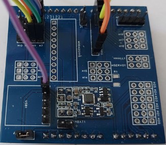
Having only 1 month for developping the project (i received the FRDM card July 27), i used an arduino shield from a precedent project.
This shield has its own power SMPS module and distributes 3,3 volts to the sensors.
picture of the arduino shield used for this project
Map of connection to sensors
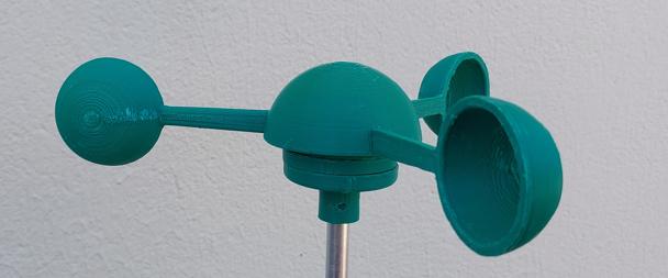
The Weathercock
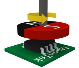
This device must detect the wind direction. For simplify the design, i use the magnetic rotary encoder SMT6701QT-STD. This component detect the position of tube magnet in rotation with Diametrical magnetization. It is possible to detect 1024 positions per 360° and the maximum speed is 55000 rpm.
This component can run with many modes : i use i2c communication for reading the position and the QFN package, a little Pcb was made with EASY-EDA.
schematic of magnetic sensor
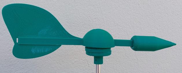
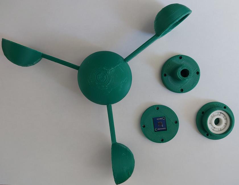
The weathercock is built in ASA material (same as ABS but UV resistant) with 3D printer, with 4 parts : a tip with a drift and a central cup with axis and magnet inside, a part with ceramic ball bearing, a part with rotary encoder and adapter for the support. The weight of the drift must be adjusted to balance it.
picture of weathercock before mount
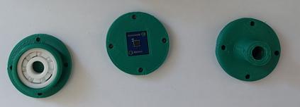
part with ceramic ball bearing, part with rotary encoder and adapter for the support
Interfacing the weathercock
The weatercock is interfaced with 4 wires (Gnd, 3v3, SDA, SCL) to i2c of Arduino Shield, this I2c is configured on FlexComm2.
The anemometer
This device must measure the wind speed.For simplify the design, i use the magnetic rotary encoder SMT6701QT-STD (the same as below). This component indicate every revolution of tube magnet in rotation with Diametrical magnetization. It is possible to work at the maximum speed is 55000 rpm. In your case, i need 3000 rpm, if the mechanic support.This component can run with many modes : i use digital mode communication and i have a pulse on W pin every rotation of magnet on the QFN package, a little Pcb was made with EASY-EDA.
The anemometer is built in ASA material (same as ABS but UV resistant) with 3D printer, with 6 parts : 3 cups fixed on a central cup with axis and magnet inside, a part with ceramic ball bearing, a part with rotary encoder and an adapter for the support.
Interfacing the anemometer
The anemometer is interfaced with 3 wires (Gnd, 3v3, WSignal) to ARD_D2 of Arduino Shield, this Wsignal is connected on Ctimer2 at 100Khz which memorize the value of the counter and generate interrupt on signal rising edge.
The Rain Gauge
This device must measure the rain quantity fall in 1 hour. The principle is based on the weight measurement of water flowing into a little container.
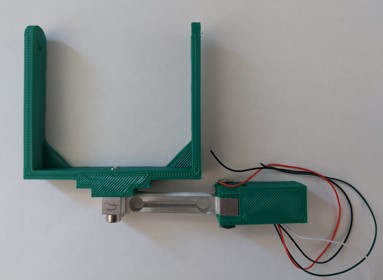
When the container reaches a given weight or after a delay, it is emptied by a small servo motor which is not in contact with the container during measurement.
The Rain gauge is built in ASA material (same as ABS but UV resistant) with 3D printer, with 11 parts :
- 3 parts for the main structure.
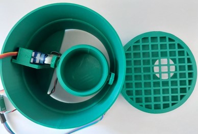
- 2 parts for the rain collector.
- The protective grid.
- The servo motor support and arm
- 4 parts for the little container with arch for rotation and arm.
- And 8 hours of printing
This device must measure the rain quantity fall in 1 hour. The principle is based on the weight measurement of water flowing into a little container.
When the container reaches a given weight or after a delay, it is emptied by a small servo motor which is not in contact with the container during measurement.
Interfacing Rain Gauge
The HX711 can be read with SPI interface and i use FlexComm1 on the mikroBus interface with 4 wires (Gnd, 3v3, MOSI, SCK).
The servo motor is connected with 3 wires (Gnd, 5v,Pwm) to arduino pin ARD_D6 form CTIMER2.
The PWM is generated with two timers CTIMER0 and CTIMER1.
CTIMER0 generate a pulse of 20ms and CTIMER1 a pulse from 1 to 2 ms.
An interrupt from CTIMER0 restart the two timer and can fix the pulse of CTIMER1 wish stop on match.
Hoop mounted on the load cell 200g
Top view of the rain gauge with grid and cup
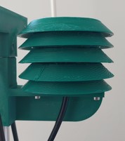
Sensors tower
The sensor tower is made up of a stack of 5 parts screwed and support allowing the passage of air and providing shelter from the rain. On each floor it is possible to install several sensors.
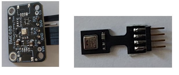
The tower is equipped with the BME688 and AHT25 sensors.
The BME688 is a sensor from the manufacturer Bosch, this sensor measures temperature, humidity, atmospheric pressure. It also has a gas measurement system to differentiate different types of gas and indicate the air pollution rate.
It requires installing a BSEC library which is based on an AI to allow learning to recognize different target gases. In our case it is the library based on gcc and M33 processor.
I use also the AHT25 for measuring Humidity and Temperature, because the BME688 warm his temperature sensor in action.
Interfacing sensors tower
A Bme688 module modified is used with no 5v to 3,3v adapter and no LDO.
The Bme688 and the AHT25 are connected to the main i2c of arduino shield.
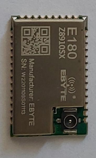
Zigbee Coordinator with NXP JN5189
In order to collect data from remote sensors based on the Zigbee protocol, we will use the module EBYTE based on the NXP JN5189 in coordinator mode.
The remote sensors consist of:
- Soil moisture, soil temperature and ambient temperature measuring devices, brightness measurement.
- Actuators of Valves with servo motors.
- High power Led light control.
Each Zigbee sensor references itself to the coordinator, which allows measurement data to be sent to it in the form of attributes. These attributes are then retrieved or modified by the MCXN947 card with serial interface in order to transmit/receive them to/from the MQTT server.
The pcb with Ebyte Module is in development.
EBYTE Module with NXP JN5189
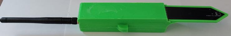
Zigbee Soil moisture and temperature sensor
State of Sky with IA and Tensor Flow Lite
(current work)
With the little camera of the MCXN947, it is possible to capture picture of the sky and after it is possible to analyse the data with an IA model.
I found a data collection of different sky and cloud and caracterisation for training the model and i must use Tensor Flow for training Lite and activating on the MCXN947.
The objective is to return information about the sky state : clear, cloudy, stormy,etc...
It is necessary to construct a box for the camera with glass and an automatic cleaning system.
Software
The software is written in C language and use MCUXpresso IDE.
I used as a basis an example putting into action an Mqtt client under FreeRtos.
After the selection of each interface (uart,i2c,spi) and corresponding hardware Pin, I created or adapted each driver for sensors.
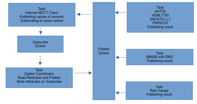
With FreeRtos it is possible to separate different tasks and transmit data via shared queues as show in the next diagram.
Conclusion
This project is not totally finish but i just started it and discover the product when i received the card July 27 from the distributor DigiKey.
The card FRDM-MCX947 is very rich in possibilities with a large number of interfaces and network management accompanied by a powerful and fast dual M33 processor.
The MCUxpresso IDE tool works correctly and the help of the examples is valuable, we regret that these examples do not include the interface configuration part.
this card is very pleasant to use and program.
Big Thanks to my wife and my daughter who agreed to let me spend lot of time on this project.
link to my web site for next project update
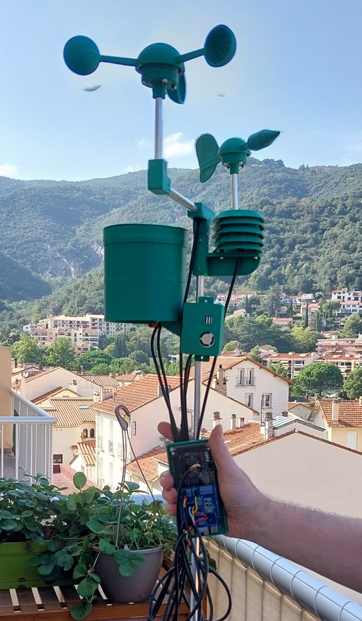
all parts mounted on frdm_mcxn947 card