MiniSolar PV Monitor is a compact energy monitoring system designed for small-scale photovoltaic setups.
It tracks four current sensors (MPPT output, battery charge/discharge, inverter 12 V/220 V line, and a 5 V auxiliary output), estimates the remaining battery energy, and triggers smart alerts based on power consumption levels.
Description
The intention of this project is to create a system for monitoring the current produced by a small solar panel (in my case 100W) as well as the current consumed by various loads (12V-220V inverter or 5v/3A auxiliary output using a StepDown converter).
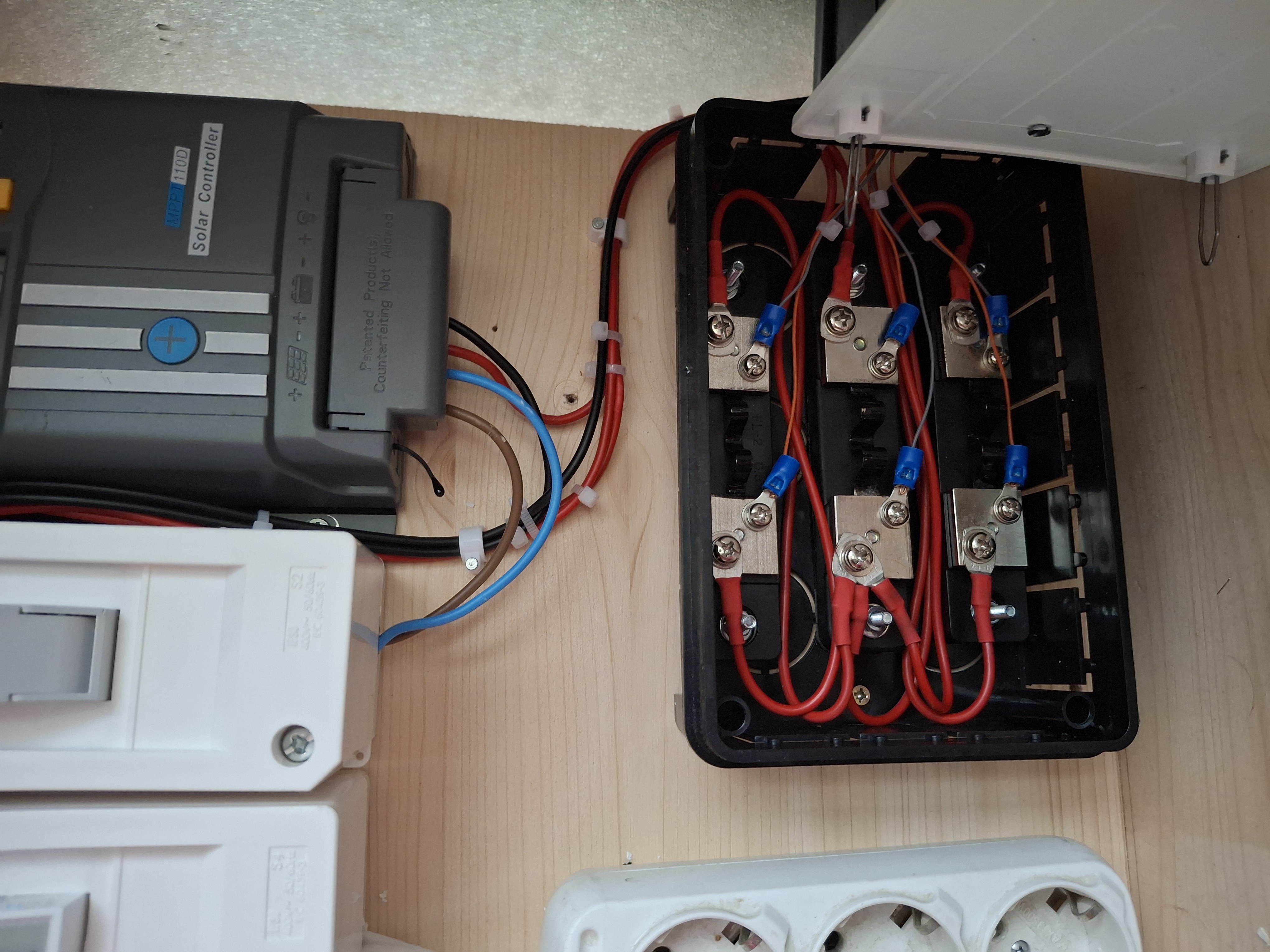
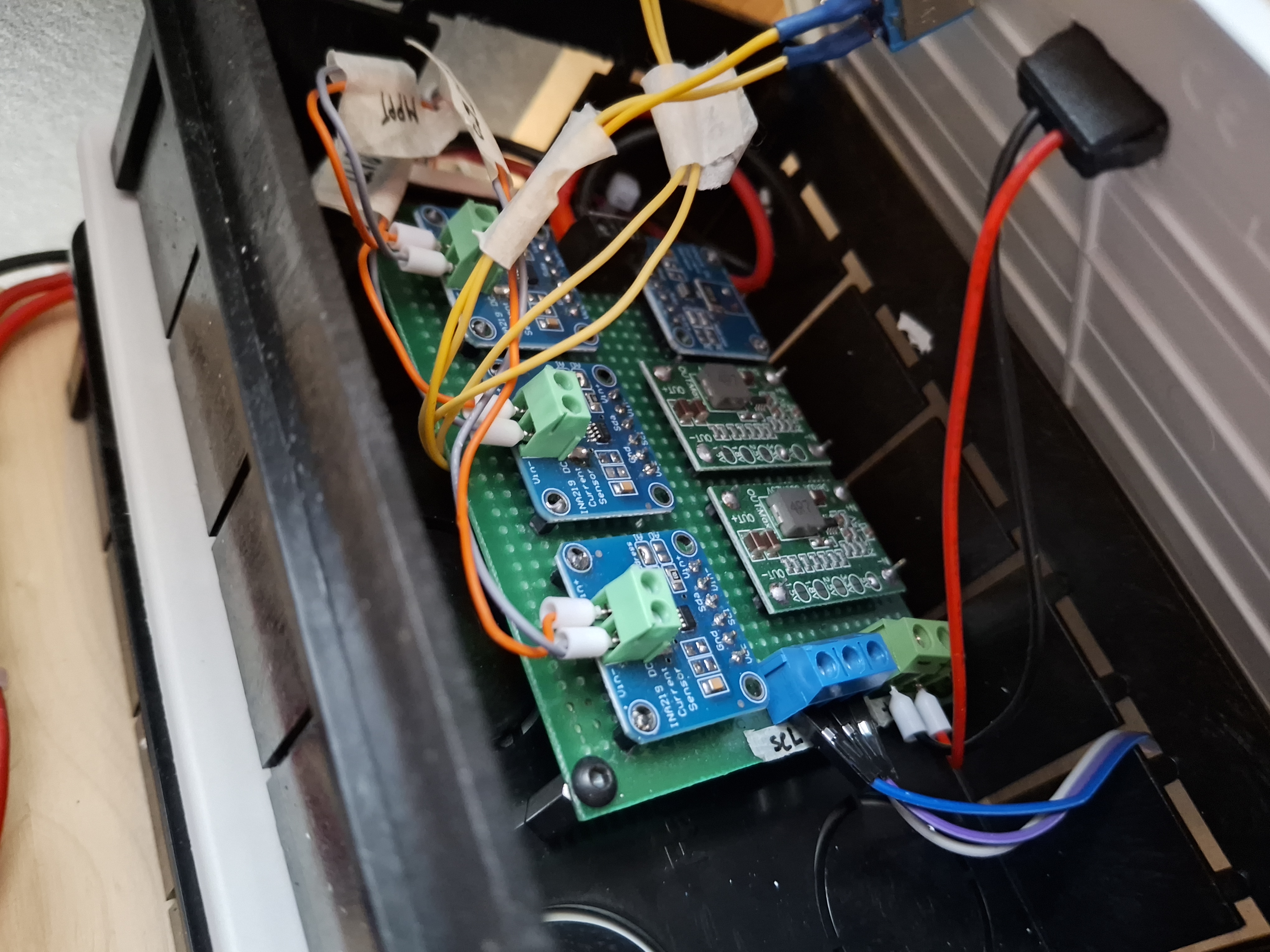
The current sensors used are of the INA219 type. I used 4 such current sensors, 3 of them with external shunt.
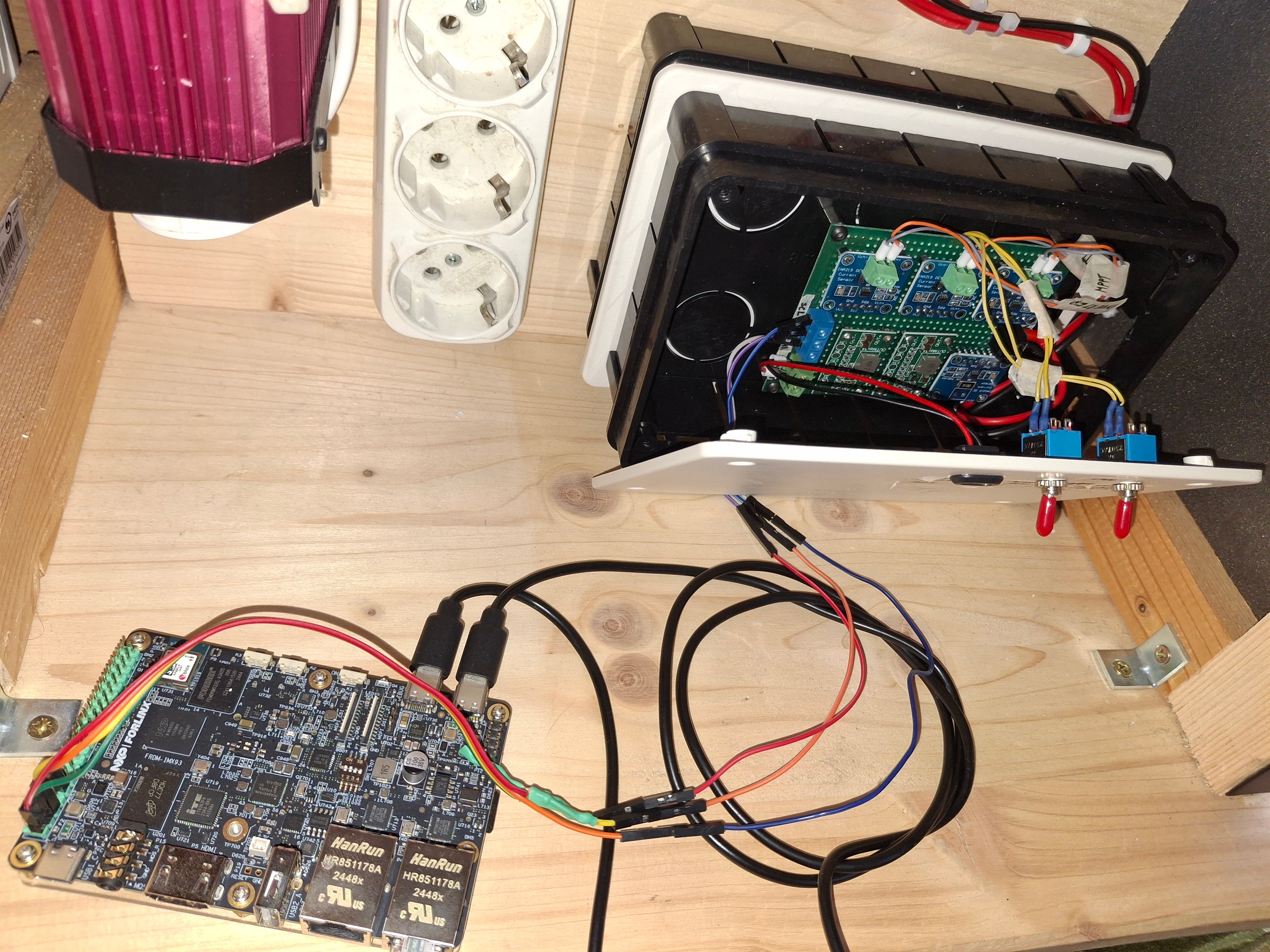
The project is made around the FRDM i.MX93 board, which is a low-cost and compact development board featuring the i.MX93 applications processor. Equipped with an onboard IW612 module, featuring NXP's Tri-Radio solution with Wi-Fi 6 + Bluetooth 5.4 + 802.15.4, the board is ideal for developing modern Industrial and IoT applications. More information abiut this board you can fine here: FRDM i.MX 93 Development Board | NXP Semiconductors
The results of the readers of the current sensors, voltage and recommendations are displayed in the console for M33 core on PC.
Components and tools
A. Components used in this project:
B. Tools:
- solder iron - generic, screwdriver, pliers, cutter;
How does the application work
This application monitors 4 current sensors, with a rate of one set of readings per second. After reading, it calculates the energy in the battery, the state of charge or discharge (depending on the direction of the current through the sensor assigned to the battery) and checks the current consumed by the inverter or the auxiliary output, generating specific messages when certain thresholds are reached (5A at 12V for the inverter and 3A at 5V for the auxiliary output).
Setup the board, tools and compile the code for M33
This board, i.MX93, is a complex development board that contain one MPU with 3 cores (one Cortex MCU M33 and 2 cores Cortex A55) and is capable to run linux. In addition, the M33 core can run code that accesses the outside world through the pins on the EXPI connector.
This project will focus on the code written for the M33 core in bare metal style.
First thing: download the SDK for i.MS93 board from here: https://www.nxp.com/document/guide/getting-started-with-frdm-imx93:GS-FRDM-IMX93?section=cortex-m33-enablement
Then follow the steps fron chapter "Cortex M-33 Enablement". The downloaded archive contain the SDK and examples for MIMX9352 processor; the esamples are in the folder /boards.
Next: setup the tool chain for M33 core. To set the development environment of an application use the "Getting Started with Mcuxpresso SDK for McIMX93-EVK.pdf" file (attached);
Programs used:
a. ARM GNU Toolchain V14.3.Rel1 - https://develooper.arm.com/downloads/-/arm-grou-toolchain-Downloads
Step 5.2 of the above document:
OBS: the path to be added to the system variables of the windows is this: C: \ Program Files (x86) \ ARM GNU Toolchain ARM-NONE-EABI \ 14.3 REL1 without the folder /bin, as it is automatically added by the script offered by the NXP (see later);
The GNU GCC RNA console can be opened from here: C: \ Programd \ Microsoft \ Windows \ Start Menu \ Programs \ ARM GNU Toolchain 14.3.Rel1 ARM-NONE-EABI
b. Mingw - https://sourceForge.net/projects/mingw/files/installer/mingw-get-setup.exe/download?use_mirror=altushost-Bul
OBS: If the download does not start, press the "Problem Downloading?" and selected "Direct Link" from the observation "please use this direct link, or try another mirror."
Follow the steps from the above document, from chapter 9.
c. Cmake - https://cmake.org/download/
Follow the steps from the above document, from chapter 9.
d. Notepad++ - Downloads | Notepad++
This is used to write the code for this application.
After all this is set, the SDK folder is copied in the path: Users \ Mihai \ Downloads or C: \ users \ Mihai \ Documents, to be able to compile successfully (in my case, the PC user is Mihai).
Important: We do this because Win11 automatically sets the Document Folder of the current user with OneDrive and the compilation tools do not work that way ...
Now, you go to the folder with the example, enter in the armgcc folder and run one of the 3 scripts used for compilation: build_all, build_debug or build_release.
OBS: I wrote the code for this application using an example from the downloaded SDK but also by the path of this example; my application is called read_multiple_ina219 and it is located in the path: Users \ Mihai \ Downloads \ sdk_25_06_mimx9352xxxxm \ Boards \ mcimx93evk \ driver_examples \ lpi2c \ read_multiple_ina219
In this moment we have the application compiled without any errors.
Transfer the code to the board and run it on M33 core
The i.MX93 board come with the linux preinstalled. We can update the linux version from the board but this is not the scope of the project. To develop the code for this board I used an PC with Win11 installed.
To transfer the file from Win11 PC on the NXP board, I used the WINSCP program, from here: https://winsscp.net/download/winsscp-6.5.3-setup.exe/download
On PC side I used an ETH-USB adapter (because I don/t have any onboard ethernet adapter on my laptop) and I set an fix IP; eg: 192.168.1.50, 255.255.255.0
An ETH cable is connected between the adapter and the NXP board, on the ENET2 port.
I power up the i.MX93 board and I openet two serial consoles: one for A55 core and another one for M33 core.
Important: The linux from i.MX93 board creates on the PC two serial ports as follows: the first is for A55 and the second is for M33. In my case: Com12 is for A55 and Com8 is for M33.
I opened two Putty instances, one for A55 and another for M33 core. From the serial console on A55 I set the IP for ethernet connection withy the PC, using the following command:
ifconfig eth0 192.168.1.100 netmask255.255.255.0 up
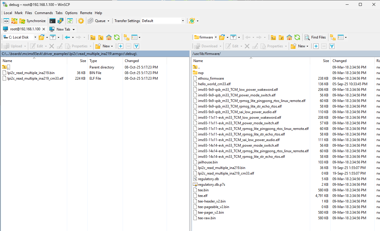
On PC side I opened WinSCP, browse in the path /lib /firmware, on the NXP board.
Then, from my folder with the code I transfer to i.MX board the following files lpi2c_read_multiple_ina219.bin and lpi2c_read_multiple_ina219_cm33.elf, from path C:\Users\mihai\Downloads\SDK_25_06_00_MIMX9352xxxxM\boards\mcimx93evk\driver_examples\lpi2c\read_multiple_ina219\armgcc\debug
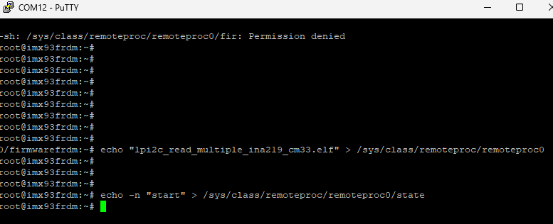
Now, we are ready to start the application on M33 core. To do that, we need to type the following commands in A55 console and monitor the respons in M33 console:
echo "lpi2c_read_multiple_ina219_cm33.elf" > /sys/class/remoteproc/remoteproc0/firmware
then start the application:
echo -n "start" > /sys/class/remoteproc/remoteproc0/state
Now, to update the application on NXP board, I use the following command, to stop the running code from M33 core:
echo -n "stop" > /sys/class/remoteproc/remoteproc0/state
and then I used WinSCP to transfer the new files from PC to i.MX93 board; then I start the new application, without power down the NXP board.
How to transfer application from PC to i.MX93 board
Start application for M33 core
Connections between mini-solar system PV and FRDM i.MX93
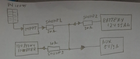
As I mentioned at the beginning of this article, the mini-solar system is made of a 100W solar panel, an MPPT charging system, a 12V/55Ah battery, a 12V to 220V inverter, and an auxiliary source that powers the current sensors and delivers a voltage of 5V at a maximum of 3A.
The sensor monitoring part is performed by the i.MX93 board by using the M33 core of this board's processor, on which it runs code written in C using ARMGCC in bare metal style.
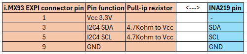
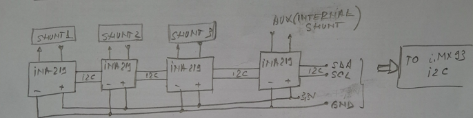
OBS: Communication with the INA219 sensors is done using the I2C LPI2C4 bus. This bus is accessible through the 40-pin EXPI (P11) connector. The connections between the I.MX93 EXPI and the I2C interface are as follows:
Below is presented the block diagram of the PV system and the connection diagram of the INA219 sensors:
INA219 sensors connections
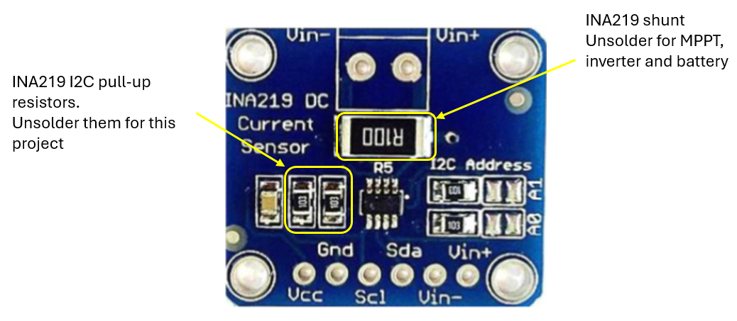
The INA219 sensors used are already mounted on a printed wiring board in the form of a module; these sensors each have the two pull-up resistors for the I2C bus. Considering that I use 4 such sensors and the fact that their power supply is from a low voltage, 3.3V, I decided to unsolder these resistors from the sensor boards and use a single pair of pull-up resistors, with a value of 4.7Kohm, connected to the i.MX93 board.
INA219 sensor module - modification
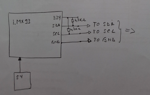
The NXP board consumes approximately 500mA at 5V, which is quite a lot for this monitoring system. Therefore, I chose to power this board from an external source, in order to be able to measure and monitor as accurately as possible the battery charging current (during the day), the current consumed by the inverter but also by the monitoring sensors as well as by the 5V/3A auxiliary output.
Below is the detailed connection diagram.
Pull-up rezistors for I2C bus on i.MX93 board side
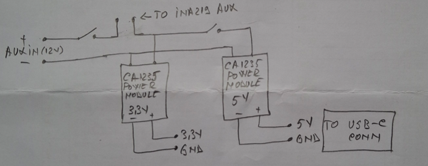
Here is presented the connections for both power supply: one for current sensors with 3,3V and one for Aux with 5V/3A:
Aux power supply and sensors power supply
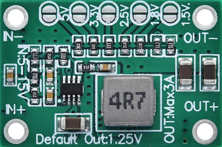
This is the adjustable power supply used to power the INA219 sensors and AUX output:
CA1235 adjustable power supply
This is the output of the monitoring system application:
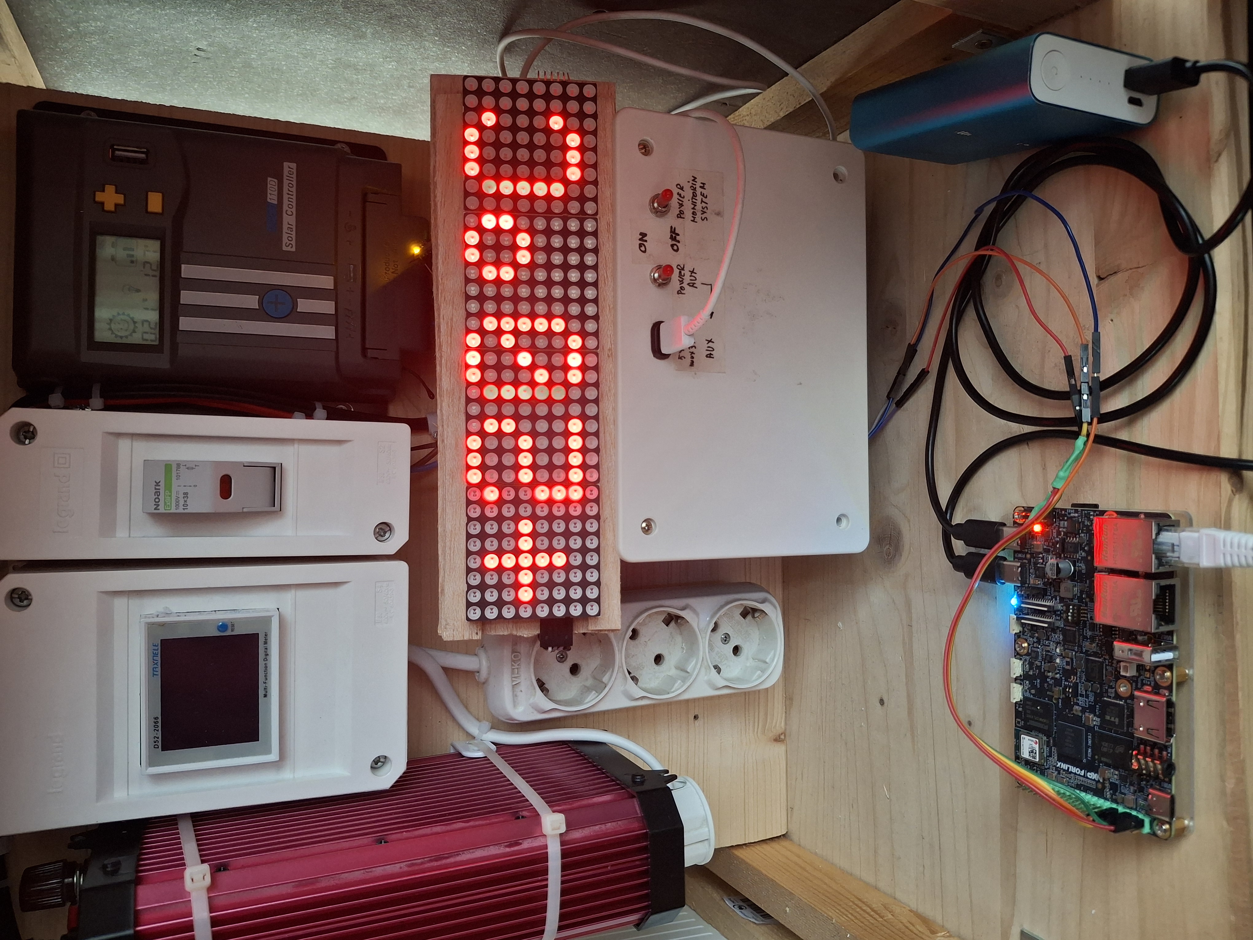
Project setup: PV with MPPT, inverter, monitoring system and load connected to Aux 5V.
Sistem started with load on Aux and i.MX93 board powered from external 5V power bank
Limitation
- the application must be started from the console of the A55 core;
- the IP for lan board shouls manually set after each board restart;
- the i.MX93 board consumes quite a lot to be permanently connected to this mini-PV system; that's why I chose to power it from the outside during the tests. In the future, if I add more solar panels, this consumption will become negligible compared to the energy produced and stored.
Next steps
- connecting an e-Ink display using the SPI connection to display information (which is now present in the M33 console);
- creating an MQTT connection between the monitoring system and the existing Smart Home system, using the WiFi or LAN connection;
- creating a web server to present the data from the console or display in the local network;
- expanding the PV system with another panel, so that the monitoring system can be powered by these panels;
- any other idea will come...