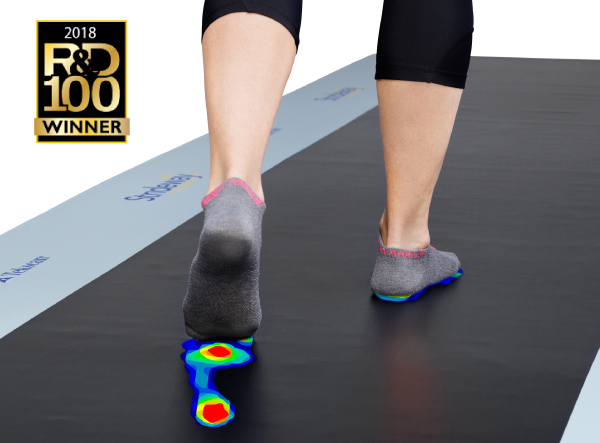
This is an overview of my process of implementing a smart gait analysis project on NXP MCX N series board, where data will be taken in by a pressure sensor insole and processed to form a heatmap, which is passed into a pretrained (through supervised learning) TensorFlow lite model, which is used to detect walking abnormalities in a person's gait.
Basic Implementation Steps
1. Model Integration
- Collect Raw Data: Gather pressure data from the sensor array.
- Normalization: Standardize data for consistency.
- Handle Missing Values: Impute or exclude missing data.
(As the board arrived pretty late due to customs, the model has not been deployed yet, and data has not been collected.)
Instead a model was made on Classifying foot positioning based on heatmaps which was then incorporated into the fashion_mnist eIQ example of the board.
Here are the steps:
1. Set Up the Development Environment
- Install Required Software:
- MCUXpresso IDE: An Eclipse-based IDE tailored for NXP MCUs.
- MCUXpresso SDK Builder: Customizes and downloads SDKs for specific boards.
- eIQ Toolkit: Provides tools for machine learning model development and optimization.
- Additional Tools:
- Install Python, OpenCV, and a terminal emulator like Tera Term for testing and debugging.
- Ensure you have an NXP account for accessing the necessary resources.
2. Prepare the ML Model Using eIQ Portal
- Download the TF lite model given here and import into the eIQ portal.

3. Export and Convert the Model
- Export the Model: After validation, export the quantized model in a format suitable for the eIQ Neutron NPU.
- Convert to TFLite: Use the eIQ Portal's Model Tool to convert the model to a TensorFlow Lite format optimized for the Neutron NPU (
.tflite file).
4. Integrate the Model into the MCX N947 Board
- Install the SDK for FRDM-MCXN947: Ensure the appropriate SDK is installed via the MCUXpresso IDE.
- Import an SDK Example: Use the
tflm_cifar10 example as a template for custom model integration. - Add Model to the Project:
- Copy the converted
.tflite model file into the project's Model folder. - Create a new assembly source file and include the
.tflite model data using the .incbin directive.
5. Update Project Files
- Modify
model.cpp: Update this file to use your model data (custom_model_data[]). - Update
model_cifarnet_ops_npu.cpp: Ensure all operators required by your custom model are correctly configured, for example, these are the operations required by the model i have created. this can be seen from the flowchart made of the the model in eIQ portal.
s_microOpResolver.AddConv2D();
s_microOpResolver.AddRelu();
s_microOpResolver.AddMaxPool2D();
s_microOpResolver.AddReshape();
s_microOpResolver.AddFullyConnected();
s_microOpResolver.AddSoftmax();
s_microOpResolver.AddSlice();
s_microOpResolver.AddDequantize();
s_microOpResolver.AddCustom(
GetString_NEUTRON_GRAPH(),
tflite::Register_NEUTRON_GRAPH());
6. Test the Integrated Model
- Prepare Test Data: Use Python and OpenCV to prepare a test image and convert it to a C array for use in the project.
- Modify
image_load.c: Update this file to point to the new image array. - Build and Debug: Use the MCUXpresso IDE to compile and run the project on the board.
- Validate Output: Open a terminal interface (e.g., Tera Term) and configure it to monitor the serial output for verification.
7. Verify and Optimize
- Verify Model Accuracy: Test with different images and scenarios to ensure the model performs as expected.
- Optimize and Iterate: Fine-tune model parameters, retrain if necessary, and iterate on your development process.
- Deploy Pretrained Model: Use a machine learning model to classify pressure data.
- Format Data: Ensure data is formatted for the model.
2. Prediction:
- Run Inference: Pass data to the model to get a classification (normal or abnormal).
Bottlenecks:

For some reason the model is too big to fit in the memory. I am still working on it, the board arrived pretty late.
for detailed steps, visit: https://www.mouser.in/applications/smart-edge-ml-nxp-frdm-mcxn947/
Pressure Sensor insole
Sensor Description for MF18-N-0A8-A01
The MF18-N-0A8-A01 is a thin-film membrane pressure sensor designed by Taiwan Alpha Electronic Co., Ltd. This sensor is ideal for applications requiring precise pressure measurement and operates over a wide range of environmental conditions. Here are the key specifications and details:
Specifications:
- Actuation Pressure: 0.5 bar
- Pressure Sensitivity Range: 0.5 to 20 bar
- Pressure Repeatability (Single Part): ±5%
- Pressure Repeatability (Part to Part): ±30%
- Pressure Resolution: Continuous (Analog)
- Stand-Off Resistance (Unloaded): >20MΩ
- Response Time: <1ms
- Operating Temperature: -20°C to +70°C
- IP Rating: IP67 (Dust-tight and protected against immersion)
- Life Cycle: 1 million actuations without failure
- Thickness: 0.38 ± 0.05 mm
Electrical Connections and I2C Interface Requirements: The MF18-N-0A8-A01 sensor has multiple sensing points, each connected via different pin pairs. Based on the provided document:
- Number of Sensing Points: 8 sensors
- Connection Pins:
- Sensor 1: P1 & P6
- Sensor 2: P1 & P4
- Sensor 3: P1 & P7
- Sensor 4: P1 & P5
- Sensor 5: P1 & P3
- Sensor 6: P1 & P2
- Sensor 7: P8 & P10
- Sensor 8: P9 & P10
Wiring and Electrical Connections:
- Power: Connect VCC to 3.3V and GND to ground.
- I2C Lines: Connect SCL and SDA to respective pins on the NXP MCX N series board, with appropriate pull-up resistors (4.7kΩ–10kΩ).
To modify the I3C sensor interface code for using the MF18-N-0A8-A01 sensor with 10 pins through an analog multiplexer, follow these steps:
Hardware Setup and Pin Connections
Sensor Connections to the Multiplexer:
- The MF18-N-0A8-A01 sensor has 8 sensing points, each output is analog.
- Connect each sensor output pair (e.g., P1 & P6, P1 & P4, etc.) to individual channels on the analog multiplexer (e.g., channels 0 through 7 for an 8-channel multiplexer like the CD4051B or similar).
Multiplexer Control via GPIO Pins:
- Connect the multiplexer select pins (A, B, and C) to three GPIO pins on the NXP MCX N series board.
- Use the GPIO pins to control which sensor's output is routed to the ADC.
Multiplexer Output to ADC Input:
- Connect the common output of the multiplexer (COM) to an ADC input pin on the NXP MCX N series board.
Power Supply:
- Ensure the sensor’s VCC is connected to 3.3V and GND is connected to ground. The multiplexer should also be powered appropriately, typically using the same voltage supply (3.3V).
Define GPIO Pins for Multiplexer control
#define MULTIPLEXER_SELECT_PIN_A 3U  // GPIO pin for multiplexer select line A
#define MULTIPLEXER_SELECT_PIN_B 4U  // GPIO pin for multiplexer select line B
#define MULTIPLEXER_SELECT_PIN_C 5U  // GPIO pin for multiplexer select line C
#define NUM_SENSORS 8               // Number of sensors connected to multiplexer channels
Initialize GPIO for Multiplexer in Main Function:
void GPIO_Init(void) {
    gpio_pin_config_t gpioConfig = {
        kGPIO_DigitalOutput, 0,
    };
    GPIO_PinInit(GPIO, MULTIPLEXER_SELECT_PIN_A, &gpioConfig);
    GPIO_PinInit(GPIO, MULTIPLEXER_SELECT_PIN_B, &gpioConfig);
    GPIO_PinInit(GPIO, MULTIPLEXER_SELECT_PIN_C, &gpioConfig);
}
Function to Control Multiplexer Selection:
void SelectMultiplexerChannel(uint8_t channel) {
    GPIO_PinWrite(GPIO, MULTIPLEXER_SELECT_PIN_A, (channel & 0x01));
    GPIO_PinWrite(GPIO, MULTIPLEXER_SELECT_PIN_B, (channel & 0x02) >> 1);
    GPIO_PinWrite(GPIO, MULTIPLEXER_SELECT_PIN_C, (channel & 0x04) >> 2);
}
The main Function incorporates the sensing and switching logic with the multiplexer.
/*!
 * @brief Main function
 */
int main(void)
{
    status_t result = kStatus_Success;
    i3c_master_config_t masterConfig;
    p3t1755_config_t p3t1755Config;
    double temperature;
    float sensorData[NUM_SENSORS] = {0};  // Array to store sensor data

    /* Attach FRO 12M to FLEXCOMM4 (debug console) */
    CLOCK_SetClkDiv(kCLOCK_DivFlexcom4Clk, 1);
    CLOCK_AttachClk(BOARD_DEBUG_UART_CLK_ATTACH);

    /* Attach PLL0 clock to I3C, 150MHz / 6 = 25MHz. */
    CLOCK_SetClkDiv(kCLOCK_DivI3c1FClk, 6U);
    CLOCK_AttachClk(kPLL0_to_I3C1FCLK);

    BOARD_InitPins();
    BOARD_InitBootClocks();
    BOARD_InitDebugConsole();

    PRINTF("\r\nI3C master read sensor data example.\r\n");

    I3C_MasterGetDefaultConfig(&masterConfig);
    masterConfig.baudRate_Hz.i2cBaud          = EXAMPLE_I2C_BAUDRATE;
    masterConfig.baudRate_Hz.i3cPushPullBaud  = EXAMPLE_I3C_PP_BAUDRATE;
    masterConfig.baudRate_Hz.i3cOpenDrainBaud = EXAMPLE_I3C_OD_BAUDRATE;
    masterConfig.enableOpenDrainStop          = false;
    masterConfig.disableTimeout               = true;
    I3C_MasterInit(EXAMPLE_MASTER, &masterConfig, I3C_MASTER_CLOCK_FREQUENCY);

    /* Create I3C handle. */
    I3C_MasterTransferCreateHandle(EXAMPLE_MASTER, &g_i3c_m_handle, &masterCallback, NULL);

    result = p3t1755_set_dynamic_address();
    if (result != kStatus_Success)
    {
        PRINTF("\r\nP3T1755 set dynamic address failed.\r\n");
    }

    p3t1755Config.writeTransfer = I3C_WriteSensor;
    p3t1755Config.readTransfer  = I3C_ReadSensor;
    p3t1755Config.sensorAddress = SENSOR_ADDR;
    P3T1755_Init(&p3t1755Handle, &p3t1755Config);

    GPIO_Init();  // Initialize GPIO for multiplexer control

    while (1)
    {
        for (uint8_t i = 0; i < NUM_SENSORS; i++)
        {
            SelectMultiplexerChannel(i);  // Set multiplexer to sensor i
            SDK_DelayAtLeastUs(100, CLOCK_GetCoreSysClkFreq());  // Allow signal to stabilize

            result = P3T1755_ReadTemperature(&p3t1755Handle, &temperature);
            if (result != kStatus_Success)
            {
                PRINTF("\r\nSensor %d read failed.\r\n", i);
            }
            else
            {
                sensorData[i] = temperature;
                PRINTF("\r\nSensor %d Temperature: %f\r\n", i, temperature);
            }
        }

        // Delay between complete sensor array readings
        SDK_DelayAtLeastUs(1000000, CLOCK_GetCoreSysClkFreq());
    }
}
I still have to make the array and the model interact, but it will take a bit time as they both are not exactly compatible.