Their lightweight structure, compact size, and ability to bend without losing performance make them ideal for next-generation products.
As demand for compact and high-performance electronics increases, the importance of proper flex PCB fabrication also continues to grow. A well-designed flexible PCB improves reliability, durability, and overall product performance. However, poor design choices can lead to cracked traces, signal issues, and shorter product lifespan.
This guide explains important flex PCB design principles that help engineers and manufacturers achieve reliable and efficient flex PCB fabrication for modern applications.
Understanding Flexible PCBs
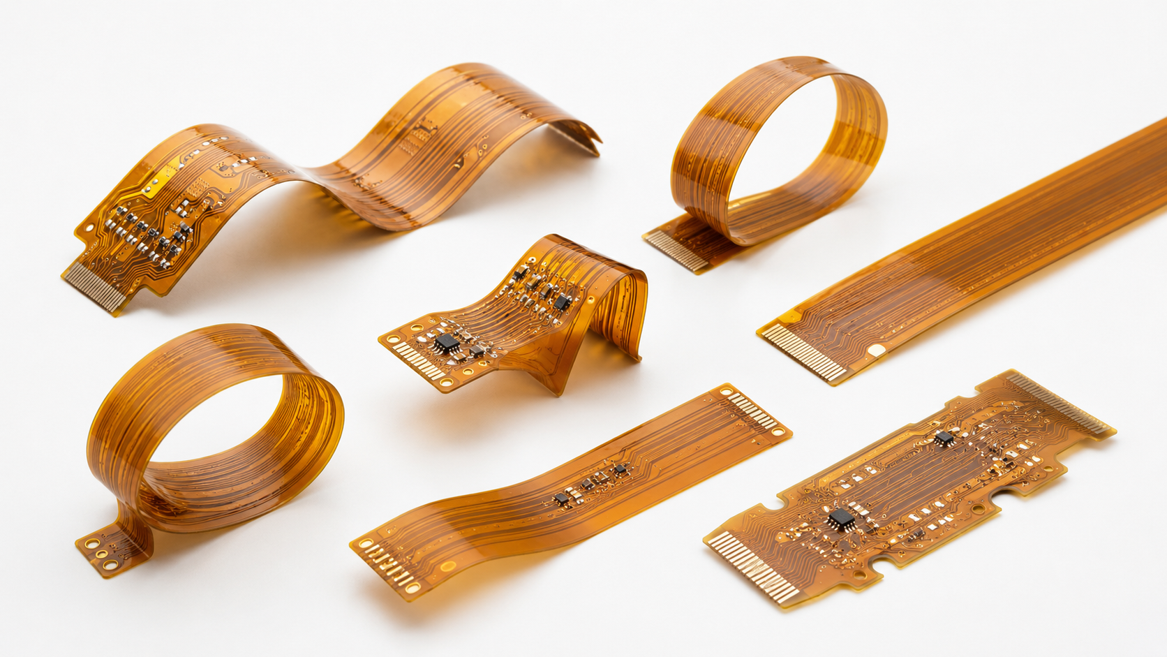
Flexible PCBs, also known as flex circuits, are printed circuit boards built using bendable substrate materials such as polyimide. Unlike rigid boards, these circuits can flex, twist, and fold to fit into tight or dynamic spaces.
Their flexibility allows manufacturers to reduce wiring complexity while improving mechanical durability. Flexible circuits are especially useful in compact devices where traditional rigid boards may not fit properly.
Advantages of Flexible PCBs
Flexible PCBs offer several benefits that make them highly popular in modern electronics manufacturing.
Key Benefits Include:
- Lightweight and compact design
- Reduced space requirements
- Improved durability under mechanical stress
- Better reliability in moving applications
- Simplified assembly process
Because of these advantages, industries across the USA are increasingly adopting flex PCB fabrication for high-performance electronic systems.
Common Applications of Flexible PCBs
Flexible circuits are widely used in industries where compact design and reliability are critical.
Medical Devices
Wearable health monitors, implantable devices, and portable medical equipment rely heavily on flexible circuits for compact and lightweight designs.
Automotive Electronics
Modern vehicles use flexible PCBs in dashboard systems, sensors, lighting systems, and advanced driver assistance technologies.
Consumer Electronics
Smartphones, tablets, cameras, and wearable gadgets often use flex PCB fabrication to support compact internal layouts.
Aerospace and Defense
Flexible circuits help reduce weight and improve reliability in aerospace systems operating under harsh environmental conditions.
Why Design Guidelines Matter in Flex PCB Fabrication
The success of flex PCB fabrication depends heavily on design quality. Even small mistakes in layout or material selection can create serious reliability problems.
Poor design can lead to:
- Cracking during bending
- Reduced signal integrity
- Mechanical failure
- Shortened operational lifespan
Proper design planning helps manufacturers avoid production defects and improve long-term durability.
Working with an experienced flex PCB manufacturer also helps ensure the design is optimized for manufacturing and performance.
Importance of Bending Radius in Flexible PCB Design
One of the most important aspects of flexible circuit design is the bending radius.
What is Bending Radius?
Bending radius refers to the minimum radius a flexible PCB can bend without damaging the copper traces or substrate layers.
There are generally two types of bending conditions:
- Static bending for occasional movement
- Dynamic bending for continuous flexing applications
Recommended Bending Radius Guidelines
As a standard guideline:
- Static bending should be at least 6 times the board thickness
- Dynamic bending should be at least 10 times the board thickness
Using a proper bending radius helps improve reliability and prevents stress-related failures during flex PCB fabrication.
Common Bending Mistakes
Some common design mistakes include:
- Sharp bend angles
- Placing components in bend areas
- Ignoring copper stress limitations
These issues can significantly reduce the lifespan of flexible circuits.
Material Selection in Flex PCB Fabrication
Choosing the right material is critical for achieving reliable performance and durability.
Polyimide Materials
Polyimide is the most commonly used substrate in flex PCB fabrication because of its excellent flexibility and thermal resistance.
Polyester Materials
Polyester materials are lower in cost but may offer reduced thermal and mechanical performance compared to polyimide.
Adhesive vs Adhesiveless Laminates
Adhesiveless laminates generally provide better mechanical reliability and thermal stability, while adhesive-based laminates are more economical.
Copper Selection
Rolled annealed copper is preferred for flexible applications because it handles repeated bending more effectively than electrodeposited copper.
Selecting high-quality materials improves both manufacturing consistency and long-term reliability.
Reliability Factors in Flexible PCB Design
Reliability is extremely important in applications where flexible circuits experience continuous movement or harsh operating conditions.
Key Reliability Considerations
- Mechanical stress resistance
- Thermal stability
- Signal performance
- Environmental durability
Proper attention to these factors improves overall product quality and reduces failure risks.
Flex PCB Stack-Up and Layer Design
Stack-up design affects both flexibility and electrical performance.
Important considerations include:
- Single-layer versus multilayer designs
- Proper grounding and shielding
- Balanced layer construction
Poor stack-up planning can create manufacturing difficulties and negatively impact flex PCB fabrication quality.
Best Practices for Flex PCB Design
Following proven design practices helps improve manufacturing success and product reliability.
Recommended Design Practices
- Use curved traces instead of sharp corners
- Keep components away from bending zones
- Optimize copper thickness carefully
- Apply strain relief methods
- Follow DFM guidelines
These techniques improve flexibility while reducing mechanical stress on the circuit.
Common Flex PCB Design Mistakes
Several design errors can reduce performance and reliability.
Common Problems Include:
- Incorrect material selection
- Poor routing design
- Improper via placement
- Ignoring mechanical stress factors
Avoiding these mistakes helps ensure successful flex PCB fabrication and longer product lifespan.
Choosing the Right Flex PCB Manufacturer
Selecting an experienced flex PCB manufacturer is essential for achieving consistent quality.
A reliable manufacturing partner should provide:
- Advanced fabrication capabilities
- Quality testing and inspection
- Experience with complex flexible designs
- Strong engineering support
An experienced manufacturer helps ensure smooth production, faster turnaround, and reliable flex PCB fabrication results.
Conclusion
Flexible PCBs continue to play a major role in modern electronic innovation. Their compact design, lightweight structure, and durability make them ideal for applications ranging from medical devices to aerospace systems.
However, achieving reliable performance requires careful attention to bending radius, material selection, stack-up design, and manufacturing quality. Following proper design guidelines helps reduce failures, improve durability, and support successful flex PCB fabrication for demanding applications.
Businesses that invest in high-quality design and manufacturing processes can achieve better reliability, longer product life, and improved performance in today’s competitive electronics industry.
Know More : https://www.pcbpower.us/blog/flex-pcb-design-guidelines-for-flex-pcb-fabrication