Track bats by making a circuit that can detect the clicks they emit.
Bats come out at night and can be difficult to spot—but with this bat detector, you will be able to track them down!
While some bats do make audible clicks, most produce inaudible clicks that are between 20kHz and 200kHz. Since vision is severely restricted at night and in caves, bats rely on echolocation, which works in a nearly identical fashion to submarine SONAR.
Essentially, the bat generates a high-frequency click that bounces off surrounding objects. The reflected click is detected by the bat and this is enough information for the bat to determine the size and type of object nearby, as well as the distance from it.
Luckily for us, these sound waves diffract and spread in mostly all directions—so if we can create a circuit that can detect these clicks then we should be able to track bats!
How Does the Bat Detector Work?
Detection of the high-frequency clicks bats emit must be done with an ultrasonic transducer for two reasons. Firstly, such transducers are very responsive to ultrasound and thus produce large output voltages upon detection (as compared to a generic audio microphone). Secondly, ultrasonic transducers barely respond to low-frequency sound (such as those found in the audible range) and thus normal talking and/or nearby sounds do not interfere with the operation of the circuit.
The transducer's output is coupled via C1 to remove any DC offset that may be present. D1 is used to remove the negative peaks on the resultant waveform as negative peaks would cause unpredictable behavior in U1A. This ultrasonic signal is amplified by U1A by approximately 23 and is then amplified again by U1B. The amplification factor of U1B depends on the size of RV1 but if a 100K potentiometer is used then the gain will vary between 2 and 100 (gains higher than 100 wills suffer from the gain-bandwidth of the LM358).
The next step is to convert the high-frequency pulse to a lower-frequency pulse for further processing. While this circuit uses an indicator LED to show that ultrasonic pulses have been detected, the circuit could easily be connected to a pair of headphones. However, the ultrasonic frequencies would be inaudible—so to make them audible, a frequency divider (4040) is used (using a division of 16 makes 200kHz signals sound like 12kHz signals).
The last step is to turn on an LED but this LED cannot directly connect to the output of the 4040 because if the counters Q4 output remains on then so will the LED. To get around this, a 555 monostable is used which turns on the LED for a brief amount of time when the trigger pin is pulsed. Therefore, even if Q4 remains on, the monostable remains off once C2 charges.
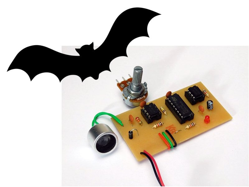
Construction
Building this circuit can be done with most circuit construction techniques including breadboard, stripboard, and PCBs. Luckily for me, my CNC is back in operation after a long hiatus and so this project was made on a PCB.
All the CNC files can be found in the project folder and include all the needed G-Code for a CNC 3020 (also included is auto leveled code).
Once the circuit has been built, it would not be a bad idea to make the circuit portable by integrating it into a box, adding a portable power supply (such as a battery), and adding a switch so that the power can be turned off when not in use.