Use analog circuitry to create a piezo electric siren that sounds like a WWII air raid siren.
Air raid sirens were instrumental during the second world war by alerting citizens of impending bombing runs. In this DIY Hacking project, we will use all analog circuitry to create a piezo electric siren.
How Does the Air Raid Siren Work?
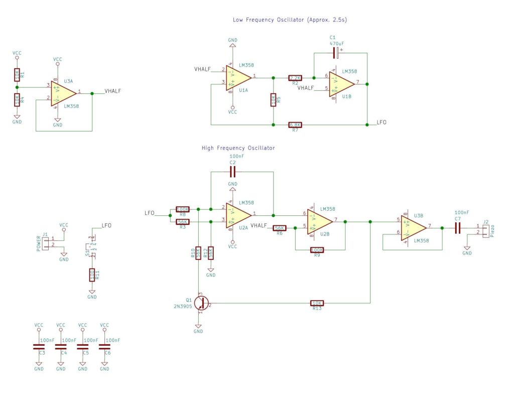
The circuit consists of two main sub-circuits: a LFO (low-frequency-oscillator) and a VCO (voltage-controlled-oscillator). The LFO circuit consists of U1A, U1B, R2, R5, and R7 with U1A being configured as a Schmitt trigger and U1B being configured as an integrator.
With the output of U1A being 0V, the negative plate of C1 begins to discharge through R2 which results in a linear increase in output voltage from U1B (the rising edge of the triangular wave). Eventually, the triangular output wave becomes greater than the upper threshold of the Schmitt trigger (U1A) which results in the output at U1A switching on. When this happens, the voltage on the negative plate of C1 begins to increase which results in the output voltage of U1B falling (the falling edge of the triangular wave).
When the output voltage falls below the Schmitt triggers lower threshold, the voltage output of the Schmitt trigger falls to 0V and this cycle repeats indefinitely. The LFOs time period is around a few seconds and this will be used to modulate the output frequency of the second circuit, the VCO.
Main Sections of the VCO
The VCO has four main sections; the integrator (U2A), inverting Schmitt trigger (U2B), reset circuit (Q1), and a buffer (U3B).
Integrator (U2A): The integrator's output will do two things depending on the state of Q1 (and the presence of an input voltage at LFO)
- If Q1 is off then C2 will charge and therefore the integrator output will fall gradually
- If Q1 is on then C2 will discharge and therefore the integrator output will rise gradually
- The rate at which the output falls or rises is determined by C2 and the input voltage LFO
- The larger LFO is, the quicker C2 charges
Schmitt Trigger (U2B): The Schmitt trigger will do two things depending on the output of the integrator
- If the integrator output crosses the upper threshold, the Schmitt trigger output will be 0V
- If the integrator output crosses the lower threshold, the Schmitt trigger output will be VCC
Reset Circuit (Q1): The reset circuit Q1 will do two things depending on the output of the Schmitt trigger
- If the trigger's output is high (VCC) then Q1 will be on
- If the trigger's output is low (0V) then Q1 will be off
How It Oscillates
The circuit oscillates in the pattern listed below:
- Q1 is on and so the integrator's output rises
- The integrator's output eventually crosses the Schmitt trigger's upper threshold
- The Schmitt trigger's output now switches to 0V
- Q1 is now off and so the integrator's output begins to fall
- The integrator's output eventually falls below the Schmitt trigger's lower threshold
- The Schmitt trigger's output now switches to VCC
- Q1 now turns on (so go back to step 1)
So while the VCO is oscillating, the LFOs output voltage is constantly changing which results in the VCOs output frequency also changing. This modulated wave is fed into a buffer (U3V) which is then fed into a speaker or piezo disc. The result is a siren whose frequency constantly changes!
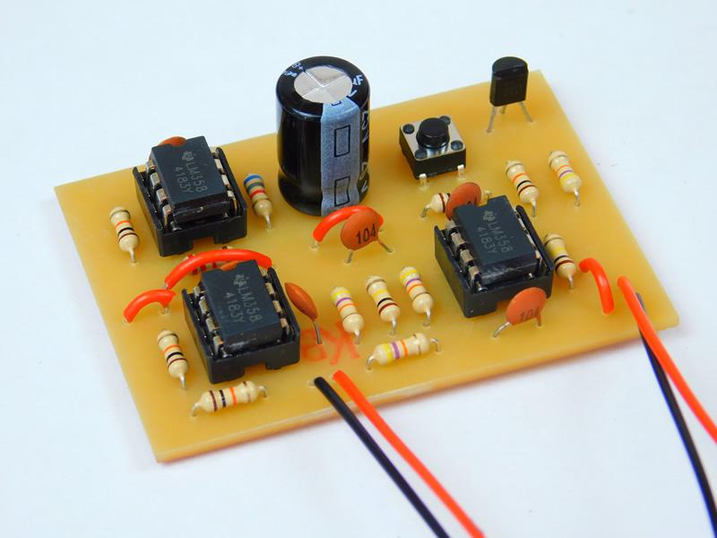
Construction
Making this project can be done with most circuit construction techniques due to the lack of surface-mount components and the use of highly common parts (i.e., LM358). Some examples of circuit techniques that work well with this project include stripboards, veroboard, matrix board, and solderless breadboard. However, in this project, I used a PCB as they are more convenient than a circuit using many wires.
All of the project files can be found in a zip below which include the KiCad schematic, KiCad PCB files, Gerber files, and the needed G-Code CNC files.