Use a standard disposable flash camera to make this coil gun that launches projectiles using a magnetic field.
Weapons and launchers have relied on chemical methods since their conception in Ancient China with the first fireworks. Now, scientists and engineers alike are working on alternatives to gunpowder and chemical-fueled weapons. One weapon, in particular, that shows promise is the coil gun, which launches projectiles using a magnetic field. So, in this project, I will show you how to take a standard disposable flash camera and turn it into a mini cannon that can launch projects several meters.
How Does the Coil Gun Work?
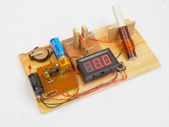
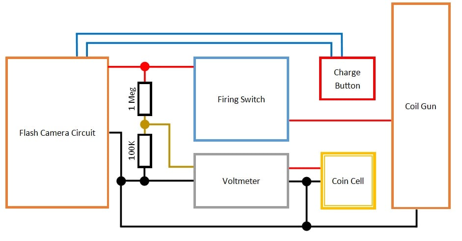
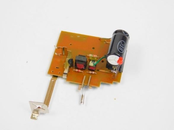
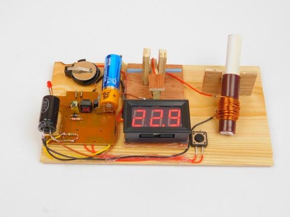
The coil gun consists of 3 main parts; the camera charging circuit, the voltage reading circuit, and the cannon/firing mechanism. The camera flash circuit involves an oscillator that pulses voltage through a small transformer found on the PCB. The transformer (a fly back variety), feeds the stepped-up voltage into a large capacitor (usually a 300V, 470uF). When the camera is triggered to generate a bright flash of light a second transformer (which is also connected to the capacitor), creates a voltage pulse that is even bigger than the large voltage stored in the capacitor. This large voltage pulse is then fed into a wire that sits behind the flash tube and this causes the gas inside the flash tube to become conductive. Since the flash tube is connected across the capacitor in parallel, the capacitor discharges through the tube and generates a bright light. In our circuit, however, we do not need the flash tube and so this is removed from the PCB along with the trigger connectors and the charging switch.
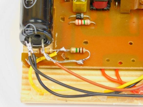
The charging pads (found on the PCB), are instead, connected to an external tactile switch that makes charging the capacitor much easier. The positive lead of the capacitor is connected to a small copper pad that sits at the contact point of our firing switch. The other side of the firing switch is then connected to the top side of the coil. The second coil lead is then connected back to the capacitor on the camera creating a pulsed electromagnet. When a projectile is loaded at the base of the coil gun tube and the system is fired, a short-lived but powerful electromagnetic field is generated which attracts the project (which must be ferromagnetic), and throws it out of the end of the other tube.
This coilgun setup also has a three-digit voltage meter which is connected to the capacitor via a potential divider made up of a 100K resistor and a 1Meg resistor. The potential divider creates a voltage that is approximately 1/10th of the voltage across the capacitor (such that 100V would correspond to 10V), and this allows for the voltage meter to take readings without breaking. The large value of the resistors also prevents discharge that otherwise could be a problem for firing. The coin cell is used here to provide a separate power source for the voltage meter. The voltage meter here requires at least 3V and the camera is powered from 1.5V. If a 3V power supply is provided for both the camera and the voltmeter then the camera does not operate properly (as it is reliant on 1.5V), however, this depends on the camera being used. Some cameras can operate on larger voltages and when they can, they usually charge very quickly.
Tearing Down the Camera
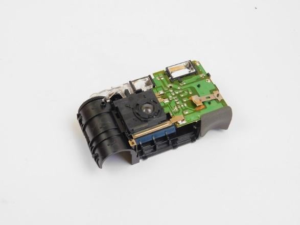
Tearing down the camera must be done with extreme caution. The internal capacitor (which can really pack a punch), could either be fully charged or have residual charge stored. Therefore, it is best to wear rubber gloves when opening the camera and then shorting the capacitor's terminals as soon as they are visible. It is not uncommon to find the leads of the capacitor very close to the edge where an unsuspecting user uses a flathead screwdriver to pry open the case and then gets a nasty shock.
It is advised that you keep the camera housing for scrapping because they contain many neat parts that can be used in so many other projects. Some parts that are scrapable include (but are not limited to), the housing itself, the camera lens, viewfinder lenses, camera mechanisms, and components that we discarded on the main PCB (such as the main flash tube).
For our circuit, we need to remove the charging button that commonly has two pads on the PCB. Sometimes, however, this could be a tactile switch which still should be removed and connected to an external tactile switch. We will also remove the trigger plates which are two small pieces of flexible material which sit close to the top of the PCB. We also need to remove the flash tube, but keep this as it is good scrapping material!
The Voltmeter
The potential divider is made by soldering the 1Meg and 100K resistors to each other and then having the series resistors connected across the terminals of the capacitor. It is important that the 1Meg resistor is connected to the positive terminal and the 100K to the negative terminal. Then, solder the ground of the voltmeter to the negative terminal of the capacitor and the measurement terminal of the voltmeter to the middle of the two resistors. Power to the voltmeter is provided by a coin cell battery but this could be any battery supply that has a voltage rating over the minimum needed voltage of the voltmeter.
The Firing Mechanism
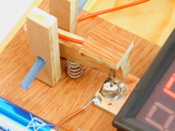
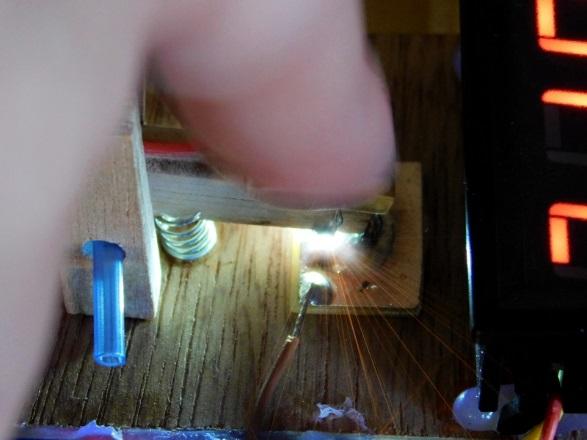
The firing mechanism in this project is custom made from a few pieces of balsa wood, a small compression spring, a cotton bud stick, a small piece of copper clad, and some wire. The switch is designed as a simple lever that when pressed, the spring compresses, and when the switch is released, the spring will return the switch to the open position. The base pad is connected to the positive terminal of the capacitor and the contact on the lever itself is connected to the top terminal of the coil gun.
The Coil Gun
The gun itself is many turns of thick copper wire around a small tube. In this example, I have used electrical tape to create ends that prevent the coil from moving and/or unwinding. The more turns on the coil, the better the coil will be as a stronger magnetic field is generated. Therefore, if you find that projectiles are not being fired out of the tube, you may have too few turns on the coil.