A step-by-step guide to make a simple remote control car that operates in RF (radio frequency).
A remote control car is a dream toy for a lot of kids, and you can never outgrow them! In this post, I will show you step by step how to make a simple remote control car that operates in RF (radio frequency). This is a very simple and beginner-level robotic project that can be made by anyone. I will be discussing the workings of all integrated circuits (IC) and modules used in this robot. And there is no programming required!
How Does the Remote Control Car Work?
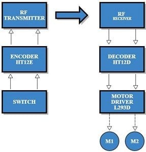
Here we will use a couple of ICs and a motor fixed to a chassis to make a remote control car. The brief idea is to transmit control signals through radio frequency and receive it through a receiver module in the car. We will have two switches in our remote control to power each motor of the car. The state of the switches (ON/OFF) is the control data. This data from the remote control is encoded before transmission, received back, and decoded again to be sent to the motor drivers. This is achieved using an RF module and an encoder (HT12E) decoder (HT12D) pair.
Using the combination of different states of the two switches, you can control the direction of motion of your remote control car. If both switches are off, both motors will be off, and the car will not move. If both are on, the car will move straight ahead. And to turn the car, switch on only the motor on the side you want the car to turn to.
Making Power Supplies for the Remote Control Car
First, we will start with the power supply circuits. Both the RF transmitter and receiver circuits need separate power supplies. The receiver circuit needs to be powered with a 12V supply and transmitter circuit with a 9V battery.
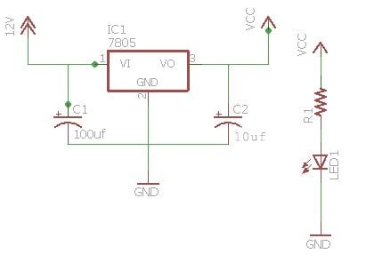
You can see the circuit for the receiver power supply on the right. Using this diagram, wire up the supply circuit. You can also add an LED via a 1K resistor to indicate the state of the power supply.
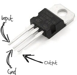
- IC 7805 regulates the 12V supply to 5V (you can also use a 9V supply here).
- You can also use 0.1uF and 470uF capacitors in the circuit and 1K resistor for status LED.
NOTE: Use heat sink for 7805 because we are dropping 7V (12-5), so a lot of heat will be produced to burn the regulator.
Making the Transmitter (Remote Control)
DPDT Switches for Remote Control
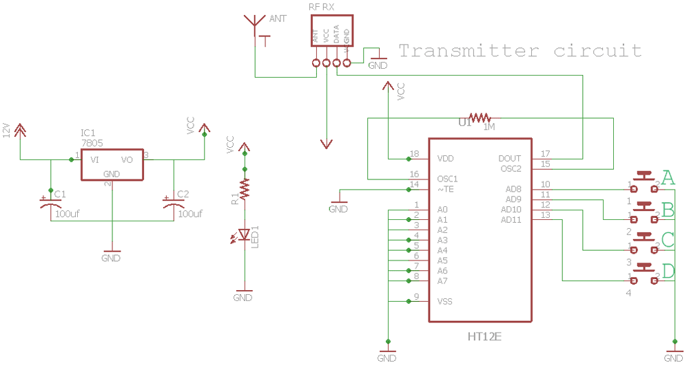
The transmitter circuit consists of ...
- HT12E encoder (Pin Out)
- RF transmitter module (Pin Out)
- 2 DPDT switches
- Power supply circuit
- 1M resistor
You can see I have marked A, B, C, D in the transmitter circuit after the switch. The same has been marked on the DPDT switch diagram. Connect the A,B,C,D on the transmitter circuit to the A,B,C,D on the two DPDT switches.
Making the Receiver Circuit
The receiver circuit consists of three ICs:
- HT12D decoder (Pin Out)
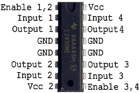
- L293D motor driver (Pin Out)
- RF receiver module (Pin Out)
Wire the circuit as per the above receiver schematic. There are two LEDs in the receiver board. One lights up when power supply is given to the receiver. The other one near the IC HT12D should light up when power supply is given to transmitter circuit. This provides you with a valid transmission (VT) when power is given at the transmitter. If not, there is something wrong with your connection or your RF TX RX module.
NOTE: Use red wires for positive and black for negative. If there are any problems, it will be easier to debug the circuit.
Choosing the Right Motor
Choosing a motor is very important, and totally depends on the type of robot (car) you are making. If you are making a smaller one, use
6V Bo motor. If you are making a larger one, which will need to carry heavy load, then use a
12V DC motor.
Choosing the Right RPM for the Motor
I have used a 12V 300RPM (revolutions per minute) motor. RPM is the number of times the shaft of a DC motor completes a full spin cycle per minute. A full spin cycle is when the shaft turns a full 360°. The amount of 360° turns, or revolutions, a motor does in a minute is its RPM value. You should be careful not to choose motors of higher RPM because it will be difficult to control. And remember, speed is inversely proportional to torque.
Debugging the RC Car (Only if There is a Problem in the Circuit)
In this section, I will discuss how to debug the remote control circuit. First of all, don’t be angry, and just keep calm! For debugging, we will split the circuit into different sections.
L293D IC
- Place the IC on a breadboard.
- Give VCC(5V) and Gnd to the IC and then give the 12V to pin 8.
- Connect the enable pins of the motors to 5V.
- Now give power to the input of one motor and check the output pins with a multimeter.
- If it shows nothing, there is problem with your motor driver. Replace it.
POWER SUPPLY
Most problems that arise in the power supply circuit are due to a short circuit. So power off the circuit and
use a multimeter to check whether there is any connection between negative and positive.
DECODER AND ENCODER (HT12E/HT12D)
The finished remote control car!
That's it! Assemble the motors, circuit, and wheels on the chassis. Rev up your motors and show your DIY remote control car to your family and friends! Watch the robot in action here: