The project is about building of a seven-segment display at home for beginners.
World over, the evolution of the electronic industry brought about the introduction of so many electronic components. There was a need for voltage regulation, voltage step down, rectification, attenuation, amplification, and so many other advances. The need for data display was not left behind and engineers and designers were tasked with the challenge of how to come up with a solution for data display. Some of the applications that needed special displays were phones, watches, calculators, etc and due to the increased demand for such products in the world, engineers came up with a display screen known as the Seven-Segment Display. In this article, we are going to focus on the seven-segment display and how we can use it to make the display of numerical characters possible.
Definition of Seven-segment display
The seven-segment display is an electronic device built to help display numerical data from zero to nine and sometimes a special decimal character. It is a semiconductor LED device with LEDs arranged in the desired order and when the current is connected to the different pins of the LEDs, they light up. This can display all the parameters represented such as temperatures, numbers, time, and many more. This component is of great use in electrical appliances more so in home appliances; water heaters, air conditioners, refrigerators, display screens, etc. In water heaters, you will come across digital tubes. Many other appliances make use of LCD screens.
The Seven-segment Construction.
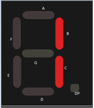
To construct a seven-segment, you will need seven small rectangular-shaped LEDs. Each LED is referred to as a segment. Sometimes an additional LED is necessary to help in displaying the decimal point. Each LED is set to its position and labeled from ‘a’ to ‘g’ and the combination is what is used to display different characters.
Each LED has one pin for receiving glowing signals into the LED while the other pins are interconnected and labeled as a common pin. The LEDs will only glow when forward-biased and by making a particular pin forward-biased, we come up with our desired character.
Seven-segment Display Working
The display has seven pins labeled “a”, “b”, “c”, “d”, “e”, “f” & “g” as shown in the figure attached below. Each pin will power a specific segment to illuminate.
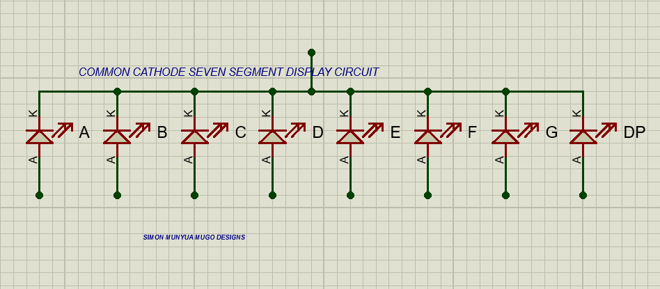
Let us make use of the common cathode segment as our illustration example. Suppose we are focused on displaying the digit ‘0’? To display ‘0’ we have to turn on a”, “b”, “c”, “d”, “e”, and “f” and then make sure that we turn off the “g”. This will give us the results shown below.
The same works when you need to display numbers such as 1, 2, 3, 4, 5, 6, 7, 8, 9, and the decimal point.
Let’s have a look at the different types of seven-segment displays below.
There exist two types;
• common cathode
• Common anode
Here all the pins of the cathodes are connected to logic 0 or ground. The anode pin is taken out and given the logic 1 or high signal so that it can illuminate a particular given LED segment ‘a’ to ‘g’.
Look at the diagram below;
Common Anode Seven-Segment Display
This type will have all the anode pins connected to logic 1 or high pin while the other pin that is cathode is taken out and given logic 0 or the ground to illuminate a specific LED segment from ‘a’ to ‘g’.
The common anode is the most preferred to the common cathode since they have more sinking than the source.
The figure below is an illustration of the common anode type of seven-segment display.
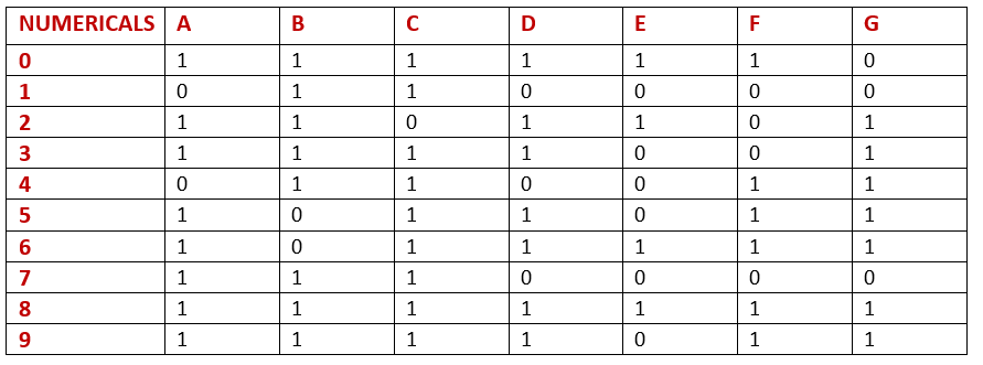
The seven-segment display can be controlled using a microcontroller such as the Arduino Uno. This can be made possible by the truth table below which helps in denoting hexadecimal or binary.
Protecting the Seven-Segment LEDs against High Currents.
If the LEDs in the seven-segment display come across high currents, sometimes they get damaged. The LEDs should be protected against such high currents. The amount of glow on the LED is directly proportional to the current flowing in the LED. If the flowing current exceeds the LED’s limit, it will end up blowing out the LED. Therefore, we need to introduce some resistors to regulate this current flow.
It is good to note that different colored LEDs will always have different forward voltage drops. For the blue LED, the voltage drop is 3.6V and for the red LED is approximately 2V.
The introduction of external resistors connected in series with every LED will serve as a precaution to regulate the forward voltage drop. For the red LED, we can calculate the resistance as follows;
If we are to use a 5V DC battery and the voltage drop across LED is 2V and each LED draws an approximate current of 15 mA for proper glow, resistance is calculated as below;
R=(5-2)/0.015 =200Ω
Hence the size of our resistor will be approximately 200 ohms.
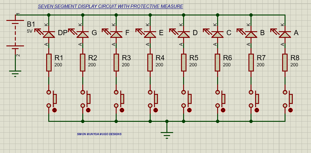
Our circuit will look like this below.
In the above circuit, we have used the common anode in seven segments where all the LEDs are connected to the resistors, and the resistor is connected to a push-button switch. We have 8 LEDs the LED on the right side is for the dot point and the rest represent A, B, C, D, E, F, and G.
From the circuit above, to display 1 on the segment then you will just need to turn on switches B and C for the provision of ground to the anode.
Sometimes you want to make things easier and you can use an IC CMOS 4511 which is a decoder driver for seven segments. The decoder is also known as Binary Coded Decimal. When this is employed, you will not have to get worried about common anode and common cathode. Another integrated IC is the TTL7447 which can handle more than one Seven-segments at a time.
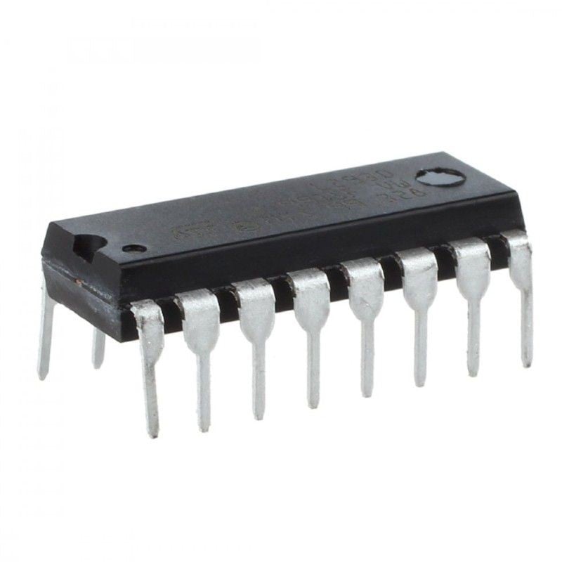
Let us have a close look at the CD4711 Integrated circuit for the seven-segment display.
CD4711 IC
It is a BCD to seven-segment decoder driver IC. It is made up of CMOS logic and an NPN transistor. It has high noise reduction and low power dissipation and can give up to 25 mA current output. It receives an input voltage in the range of 3 V to 18V.
Its main purpose is driving displays such as the seven segments.
It is a 16-pin IC with the pin out listed in the image below;
The driver picks four inputs and gives out seven outputs. The input side is labeled A, B, C, and D. the decoder will pick the four bits and convert them to necessary decimals for displaying on the seven-segment.
Below is the circuit connection for the Seven-segment using the CD4711 ic.
Although the LED-based seven segments are common, they are being replaced by liquid crystal displays because of the difference in power consumption.
Conclusion
We have introduced what a seven-segment is, and how to construct it. The different types of configurations available and how to integrate the seven-segment with an IC driver.
The content is suitable for DIY makers, especially beginners.