Part three of a series on how to build your own computer from scratch, based around the Z80 CPU.
In this series, Robin builds a Z80 computer from scratch. Catch up with parts 1 and 2.
In the last project, we added memory to our Z80 computer. But unless we can program the ROM, our computer will just sit there idle! In this project, we will make a simple EEPROM programmer that will allow us to program the EEPROM with our own Z80 programs.
Schematic
How It Works
This project is comprised of three parts: the physical circuit, the microcontroller software, and the VB.NET windows application that allows us to transfer data to and from the ROM chip being programmed.
The Circuit
The programmer circuit consists of only a few ICs and passive components, including resistors, capacitors, and LEDs. The main controller is the PIC16F1516, which handles the serial connection, data transfers, and memory controlling. Since the memory IC requires many address pins, a 74HC4040 counter is used to point to the current memory address instead of using many IO pins from the microcontroller. This means that while only two pins are needed to get to the correct address (Clock and Reset), the microcontroller cannot jump to a specific address. Instead, if the controller needs to get to a specific address, the counter needs to be reset, then the clock, until the correct value has been reached. Luckily for us, we sequentially program and read the EEPROM, so this is not needed. Besides the 4040 and the memory IC, the only other components are indicator LEDs to show the current state of the programmer and simple power regulation via the 7805.
The Microcontroller Code
While the entire code for the microcontroller will not be explained (due to its size), the core parts will be covered. Upon first starting up, the microcontroller goes through its configuration, which enables the UART port, enables interrupts, and configures the internal oscillator for maximum frequency (approximately 16MHz). After the initial configuration, essential variables are assigned needed values, and global interrupts are enabled. With everything set up correctly, the microcontroller sits in a connection request loop, which essentially is a loop that waits for the host program (the VB.NET application) to send 0x01 over the serial port. Once the host program requests to connect, the microcontroller sends back 0x01, which is the connect acknowledge to inform the host program that the connection has been accepted.
At this point, the program sits in a loop waiting to enter program mode (done by sending 0x02), and then when the byte to write to the EEPROM chip has been transferred (in the form of two ASCII characters such as FF or 3C), the software converts the two ASCII characters into a single byte and proceeds to write the byte to the EEPROM.
The interrupt routine also contains specific routines for specific command bytes sent by the host program. For example, 0x03 indicates the end of transmission, which is important, because it flags “data ready” so the byte needing to be written to the EEPROM can be written. Another command, 0x04, resets the memory address counter which is done before writing so the program is stored in the right place in the EEPROM. 0X05 informs the microcontroller that the programming sequence has been completed, while 0x06 informs the microcontroller to read the data found at the current address and then increment the counter to point to the next memory address.
The Host Program
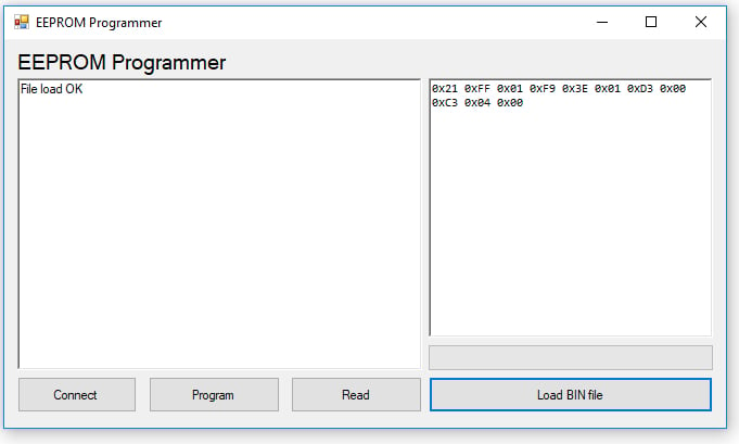
The host program, written in VB.NET, is a form application that allows us to stream our Z80 programs to the EEPROM. The main controls for the program are the Connect, Program, Read, and Load BIN file buttons. There are two rich edit boxes for displaying information with the left windows showing messages and the right windows showing both read data and the contents of a loaded BIN file to be programmed.
When the connect button is clicked, the VB.NET program cycles through all serial ports found by the operating system, and the byte 0x01 is sent to each serial port. The port that responds with 0x01 is our programmer, and thus once 0x01 is received, our program knows we have a successful connection.
The load BIN file button opens an open file dialogue that allows us to load our Z80 program (made using tniASM). Once loaded, the program streams the binary data into a byte array, then displays the contents of the file to the binary view rich edit box (large right window). However, we can't directly stream the byte data to the rich edit box, since the byte data is not in a human-readable format, and therefore we have to convert the data to ASCII. This is done by splitting the byte into two nibbles and adding offsets to convert them to characters such as 0 and F.
When you click the program button, the VB.NET program starts by resetting the address counter on the programmer circuit. This ensures that we program from address 0x0000. Once reset, the application starts streaming the data over serial, but not before converting the byte values to a human-readable ASCII form. This is done because data values between 0x00 and 0x06 are specific commands that would confuse the programmer if we had a raw value of 0x00 to send. So, when the microcontroller receives two ASCII bytes (which represent a single byte), it converts them back to the single byte, which is then programmed into the EEPROM.
The read button, once clicked, resets the address counter on the EEPROM programmer and starts requesting bytes (command 0x06). The data that streams from the microcontroller is not ASCII encoded, because the host program does not use command bytes, but the bytes are still converted into a human-readable format so they can be displayed on the BIN rich text box. Note that the number of read bytes is 256 (between 0 and 255) because our Z80 computer uses a 256 byte ROM space. This, however, can easily be changed by changing the for-loop found at line 162.
The host application is far from being a fully featured EEPROM programmer, but this basic setup will have you programming EEPROMs with your own Z80 code. Features you could add include verification, multiple devices, individual byte editing, and offset control.
tniASM
You can make Z80 programs for our computer with many different tools, but the one that I personally found the most useful is tniASM. This assembler is free for use and can be downloaded here. However, this is a command-line program, which makes things a tad complicated when trying to make programs, so included in this project is tniASM with a compile bat file. All you have to do is stick your Z80 assembler code in the main.asm file (found in source), and once written, run Complie.bat. This will output a bin file called ROM.bin, which is found in the Bin folder, and this file is then loaded into our VB.NET program. In the next project, we will look into making some basic Z80 programs to test our hardware!
Construction
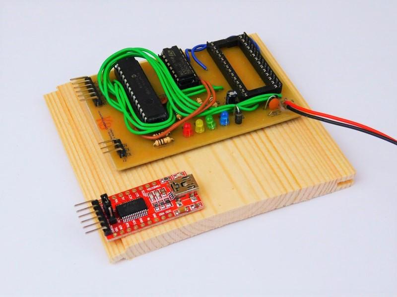
You can construct this project using many different circuit construction techniques, including stripboard, breadboard, matrix board, and PCBs. For this project, I have used a PCB, for a couple of reasons. First, because wiring is not exactly fun, and second, because of the surface mount 7805 used. Since the PCB design is single-sided, wires are needed as jumpers, with the main bulk of the wiring being for the data bus that transfers data between the PIC and the EEPROM.
Since this project also needs an FTDI to transfer data between the circuit and the computer, a project box would be ideal. However, for the sake of demonstration, the circuit has been mounted on a single piece of wood. The EEPROM IC holder is a 28 DIP socket, which is sufficient for prototyping, but if you're going to use this programmer frequently, you'll want to use a zero insertion force (ZIF) socket. I used a standard socket, since I don't have any ZIF sockets, and I have another programmer for programming EEPROMs. It is not entirely ideal, though, because it needs a parallel port, and these are now rather rare.
The EEPROM programmer software
Topside of the main circuit
Underside of the main circuit
Downloadable Files
Related Articles