Use the TCS3200 module to make a color sensor for your project.
Do you have a project that requires some form of color recognition? Are you in need of sorting your Skittles? You should look into the TCS3200 color sensor! In this project, we will look at how to use the TCS3200 color sensor.
Schematic
How the Color Sensor Works
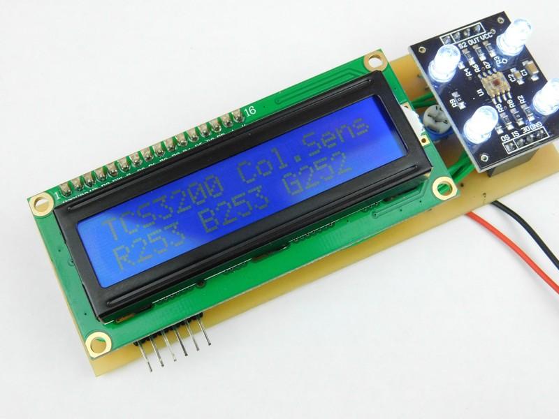
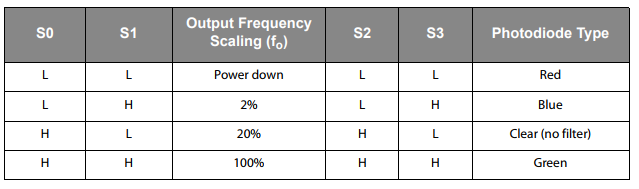
The core of this circuit is the TCS3200 color sensor module, which is controlled by a PIC16F1516. For the sake of demonstration, this project also has a 16x2 LCD display for showing the individual color outputs (red, green, and blue). The sensor itself consists of an array of 8x8 photodiodes with 16 photodiodes having red filters, 16 having blue filters, 16 having green filters, and the remaining 16 having clear filters. These photodiodes are connected to a current-to-frequency converter, which produces an output square wave whose frequency is proportional to the intensity of the chosen filter. Only one color filter can be selected at a time, and this color channel is picked by using two pins: S2 and S3. The base frequency of the output is determined by the two pins S0 and S1 (see the tables below).
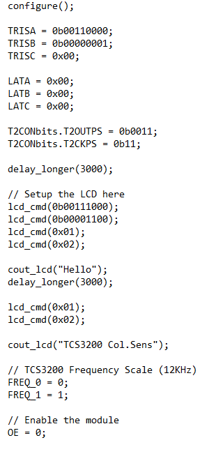
The firmware in the PIC starts by running some basic configuration code that sets up ports, configures peripherals, and sets variables to known values. After the device is configured, the PIC then configures the 16x2 LCD so that it is in 8-bit mode, two lines, no cursor, and no blinker. With the LCD sorted out, the TCS3200 sensor is configured to use 20% frequency and its output enabled by setting the OE pin low.
The next step after this is to run the infinite while loop that just about every microcontroller project runs. On each iteration of the while loop, each color sensor is picked, tested, and then converted into an ASCII string for printing to the display. Testing the frequency is rather easy when you have a timer, and in this project we use timer 2.
To measure the frequency, we will time for how long the square wave is on or off. But to do this accurately, we have to get ourselves into a known state, otherwise we may only end up measuring a small portion of the on/off time. So, to do this, we wait for the falling edge of the signal, then we wait for the rising edge, then we wait for the falling edge. Once the signal is low, the timer starts and begins counting. When the signal goes high, we stop the timer, and TMR2 will have a value whose value is inversely proportional to the frequency.
Construction
This project can be constructed using most circuit construction techniques, thanks to all of the parts used being available in through-hole parts. Such circuit construction techniques include breadboard, stripboard, matrix board, and PCB. In this project, I have used a PCB, as the 7805 used here is an SOT-89 part, which has a very small footprint and is surface-mount.