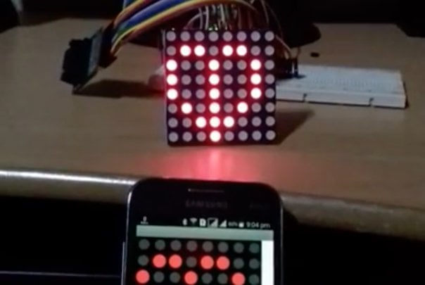
An Android app uses a virtual LED matrix to update a physical LED matrix directly from a mobile device.
In this project, we use an Android app that uses a virtual LED matrix so we can update the character seen on the LED matrix from the mobile device directly.
We will describe the circuit used to go from drawing a character on an Android App, sending it to an Arduino UNO via Bluetooth, then to a GreenPAK5 via I2C which fits data to display the character on an LED matrix.
The project consists of three stages:
- Building the Android application.
- Creating a GreenPAK design.
- Creating the Arduino code.
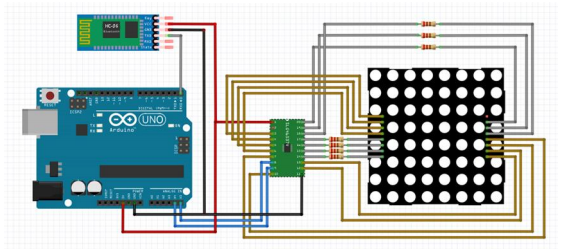
Circuit Schematic
How Does the LED Matrix Work?
LED dot matrices are very popular because they are visible in a variety of ambient conditions. In a dot matrix display, multiple LEDs are wired together in rows and columns in order to minimize the number of pins required. For example, an 8×8 matrix of LEDs has the cathodes together in rows (R1 through R8) and anodes in columns (C1 through C8). Each LED is addressed by its row and column number. In this example, we are using what is referred to as a Common Row Cathodes LED Matrix. To illuminate an LED pixel in the matrix, a high signal is applied to the anode (column) and a low signal is sent to the cathode (row). When we want to show characters or symbols, we typically need to illuminate numerous pixels. In this case, we divide the picture into sections, and we illuminate every row in a fast loop separately.
The human eye can detect LEDs blinking at low frequency, but at more than 20Hz, the full character will appear with less flicker. In this design, we will control an 8x7 LED matrix, as the last column C8 will be omitted because of a limitation of IO pins.
Android Application
For this first stage, an application for Android devices is built to send data to the Bluetooth module. The app will have the graphical interface that the user sees.
The app interface has 56 buttons. Each button represents a pixel in the LED matrix, hence, each one will be represented by a binary variable with two states (on=1, off=0).
Each LED's row is represented by one byte (bit for pixel). To find the byte's value, we multiply every button state by the significant bit and then we take the sum of the products.
p1 through p64 are binary variables hold buttons states (on =1, off=0).
B1= (P1 X 1)+(P2 X 2)+(P3 X 4)+(P4 X 8)+(P5 X16)+(P6 X 32)+(P7 X 64)+(0)
B8= (P57 X 1)+(P58 X 2)+(P59 X 4)+(P60 X 8)+(P61 X16)+(P62 X 32)+(P63 X 64)+(0)
After this calculation, the character will be represented by 8 bytes (B1 through B8) which will be sent to the Bluetooth module.
The app can be made using the MIT App Inventor with ease, no prior programming experience is required. The app Inventor lets you develop applications for Android phones using a web browser with programming blocks.
To create an Android Application, a new project has to be started and the visible components need to be removed from the designer screen.
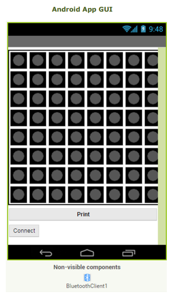
Then 58 buttons need to be created: 56 buttons will be for the LED matrix, one will be for the list pickers for the Bluetooth devices (connect), and the last button will be used to send data via Bluetooth (print). We also need a Bluetooth client. Below you can see a screen capture of our Android Application’s user interface.
To start programming, the “Block” button needs to be clicked. By dragging and dropping, we can add components from the bar on the left side. The global variables will be added and on-click functions for each button have to be built which will be used to change colors and/or to save the button state (on/off).
For different buttons, the process can be repeated by changing the button number and the global variable each time.
Once done, the mathematical equation needs to be built, which will gather every row's bits in one byte (B1..B8 equations). The 56 button states will be formed in 8-byte variables.
Finally, the app will send the 8 bytes using Bluetooth as a list of bytes when the print button is clicked.
GreenPAK Design
The Android application sends data to the Arduino, and then from Arduino to GreenPAK via I2C connection. The I2C interface in the GreenPAK SLG46537V is very powerful because it can read and write all its configuration bits (including output states and ASM RAM). The I2C write command begins with a start bit, followed by a control byte, word address byte, data byte, and stop bit.
The GreenPAK IC can be easily programmed by downloading the GreenPAK software to view the pre-made Drawing Characters on an Android App and Displaying it on LED Matrix Desing file. Connect the GreenPAK development kit to the computer, pop an unprogrammed GreenPAK IC into the development kit socket and hit program. The IC will automatically be programmed.
Once the IC is programmed, you can keep the IC in the development kit socket for easier access to the pins, or for volume production, you can create a tiny PCB board to access the chip.
With the GreenPAK IC programmed, now you can skip to the next step.
If you would like to better understand and modify the circuitry here is an overview of how the GreenPAK was programmed.
The Android application sends data to the Arduino, and then from the Arduino to the GreenPAK via I2C connection. The I2C interface in the Silego SLG46537V can read and write all its configuration bits (including output states and ASM RAM). The I2C write command begins with a start bit, followed by a control byte, word address byte, data byte and stop bit. In GreenPAK, we start designing the I2C block. This block is enabled from the properties bar and then the control code is chosen. Then two wires will be connected between pins 8, 9(SCL, SDA) and from the control code list, the device address is chosen (a number from 0 to 15). In our project, 0 (0b0000) is selected.
A controller that will show bytes in rows needs to be made. For that, a State Machine block (ASM) has to be used. There are 24 state transition inputs, 1 nRESET input, and 8 output lines. The ASM block is defined using state transitions and state outputs. Every state will represent one row and it will show the byte that is received from the Arduino. The movement from the current state to the next one happens by applying a high signal on the next state enable's pin and a low signal on the current state enable's pin.
Take State 0 for example, its box contains a state 1 arrow as the next state. This means that in order to transition from State 0 to 1, the input of the State 1 arrow needs to be high when the ASM is in state 0. A counter with pipe delay will be responsible for generating the pulse. CNT4 is used to generate a 0.32ms timer that is used as the one-shot pulse width for all the states. Since the ASM’s inputs are level triggered and not edge triggered, the CNT4’s output can’t simply be used as the trigger for all state transitions (because it would cause almost instantaneous transitions from one state to another instead of waiting for 0.32ms between transitions). To address this, the Pipe Delay macro-cell is used to generate 2 complementary outputs with 50% duty cycle. While one signal is used to transition from even to odd-numbered states, the other is used to transition from odd to even-numbered states.
In every state, the ASM output will be the row byte which we want to show, so we connect the ASM outputs directly to the GreenPAK output pins which are in turn connected to the LED matrix columns, (pins 14 to 20).
With every state, one row that is related to the state has to be activated and because the cathodes are wired together in rows, the active signal for rows is low; hence, a low signal is applied to the related row. A series of 8 DFF will give a low signal on one output (with every CLK) while giving a high signal for the other outputs. This low signal will move from one row to the next with every rising edge's CLK. To do that, the output of every DFF is connected with the next DFF's Dpin.
Arduino Code
The Arduino, which is connected to the Bluetooth module, will receive the 8 bytes using the UART interface. It will perform data fitting and will send them to the GreenPAK5 using I2C.
The HC06 module used for Bluetooth communication uses the UART for communication protocol with a 9600 baud rate. That number will be used in the code.
The Arduino UNO has a serial interface connected to pins 0,1 (RX,TX) to make the UART connection with other components. So the Bluetooth module TX will be connected to the Arduino RX (pin 0). Bluetooth module TX ----> Arduino RX (pin 0). After receiving data bytes, the Arduino has to be used to send these bytes (using i2C protocol) to GreenPAK. To make this easier, we used Silego's Arduino Library.
The code can be seen here:
#include <Wire.h>

#include "Silego.h"                                // Include Silego header file

#include "macros/SLG46531.h"           // Include macros for SLG46531 byte rows_byte[8];

//matrix to hold rows bytes int i=0 ;

//counter boolean s=0;

//state flag

// Create an instance of Silego class called // "silego" with device address 0x00 Silego silego(0x00);

void setup()

{

Serial.begin(9600);

 //Bluetooth module's baud rate

 }

 void loop() {

while(Serial.available()>0) //receiving bytes coming from

{

//Bluetooth rows_byte[i]=Serial.read(); delay(5); i++; s=1;

 //set flag

 }

if(s==1)           // send bytes to GreenPAK using I2C

{

silego.writeI2C(ASM_STATE_0, rows_byte[0]);

silego.writeI2C(ASM_STATE_1, rows_byte[1]);

silego.writeI2C(ASM_STATE_2, rows_byte[2]);

silego.writeI2C(ASM_STATE_3, rows_byte[3]);

silego.writeI2C(ASM_STATE_4, rows_byte[4]);

silego.writeI2C(ASM_STATE_5, rows_byte[5]);

silego.writeI2C(ASM_STATE_6, rows_byte[6]);

silego.writeI2C(ASM_STATE_7, rows_byte[7]);

s=0;  // Reset flag

i=0; // Rest counter

} }
An LED matrix driver has been created that can be controlled from a controller via the I2C protocol. An Android app has also been built with a virtual LED matrix to draw characters and to display them. The Silego GreenPAK Configurable Mixed signal IC (CMIC) has a variety of digital and analog components that facilitate the creation of moderately complex designs. It also has the I2C interface which allows control of GreenPAK registers from any I2C master.