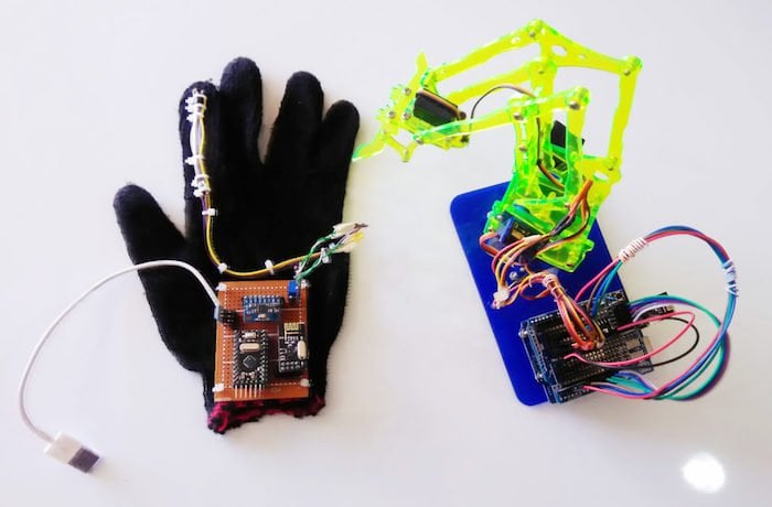
For this project, I'll be controlling a 3D printed robotic arm. But instead of a simple button + joystick setup, I'll be building a hand gesture robotic arm just like how this bot was controlled. Would you like to build one? Here's how I did it!
Hand Gesture Robotic Arm Theories
The idea is to use motion and bend sensors to detect my hand movements. My robotic arm has four servo motors so I need to have four inputs for control. I decided to combine the two arm extension servos so I will only be using three inputs instead. These inputs are then wirelessly sent to the robotic arm receiver circuit.
For motion detection, I decided to use an MPU6050 accelerometer plus gyroscope which is easy to use with Arduino. I also used the MPU6050 for my Arduino self-balancing robot. I could have purchased a bend or flex sensor but decided against it since it's $20 and I only need one to control the grip. So I made my own optical bend sensor using an IR transmitter-receiver pair and a control circuit. More details of this DIY bend sensor in the "construction" section below.
The wireless transmission is made possible by two NRF24L01 transceivers that operate at 2.4 GHz. I thought this was a good choice since lower frequencies might succumb to interference from the servo motors. The 50 m or so range was also enough for the project.
Construction and Diagrams
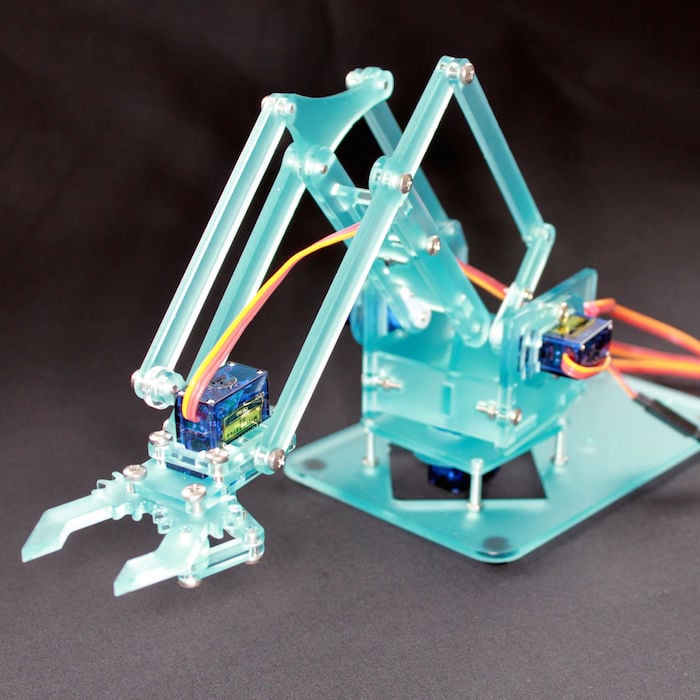
The robotic arm I used is based on phenoptix's MeArm. If you have a 3D printer available, you can build your own using these designs or you can buy robot arm kits. Whichever the case, it will still work with the circuits on this project as long as the arm has four hobby servo motors.
Controlling four servos would require power that the Arduino may not be able to supply if it's only power source is its USB connection to the computer. Thus, I used a separate 5V DC power source.
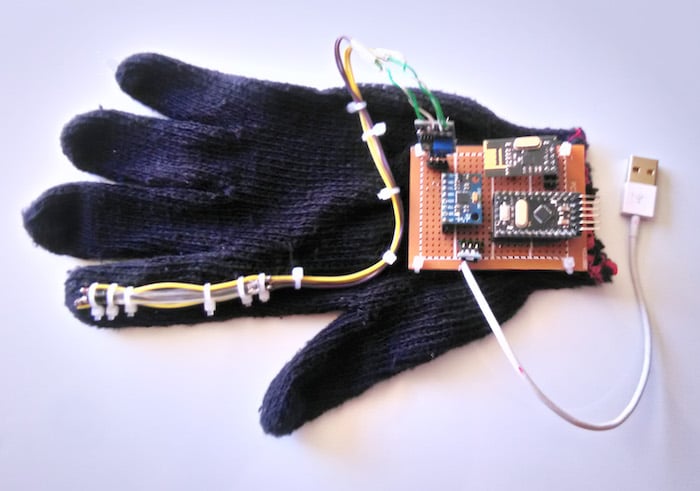
The transmitter circuit should be small enough to fit on the back of my hand but with enough space to fit all the components. The MPU6050 and the Arduino Pro Mini can be powered from 5V but the NRF24L01 can't unless you buy a special adapter. So I decided to add in a 5V to 3.3V converter module which uses the AMS1117. Here's what my transmitter board looks like on top of the glove:
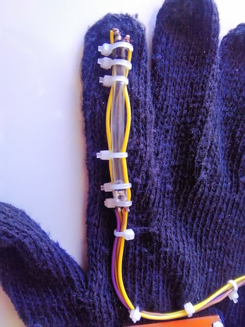
The bend sensor used an IR transmitter and receiver placed on the ends of a transparent tube:
This includes a control circuit to adjust the sensitivity very much like this one:
Basically, the amount of IR signal on the receiver will vary according to how bent the tube is. If the tube is straight, the receiver receives maximum IR signal. On the other hand, bending the tube will impede the IR signal and will result in a smaller voltage received at the receiver.
As for the receiver circuit, I decided to use a Proto Shield to keep things neat and tidy. Here's my setup and Fritzing diagram:
The Radiohead library was used for the NRF24Lo1 while the MPU6050 library from my other project was used. There's a transmitter sketch for the controller and a receiver sketch for the robotic arm. I didn't use the built-in servo library because it has issues with the Radiohead library, particularly on using the ATMega328p's Timer1 peripheral. Instead, I created a simple function that generates pulses through delays.
You can download all necessary code files from my github repository.
Video
Here's the finished robot in action!
If you have questions regarding this project, feel free to drop comments below!