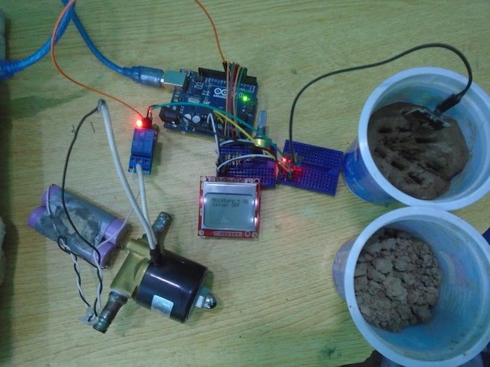
Make an automatic irrigation system that will sense the moisture of the soil and open or close the valve accordingly.
In this project, we are going to make an automatic irrigation system that will sense the moisture of the soil and open or close the valve according to it. The moisture value and the valve status will also be shown on the Nokia 5110 LCD.
If you'd like to know more about using the FC-28 soil moisture sensor, check out this tutorial: DIY Soil Moisture Testing with Arduino.
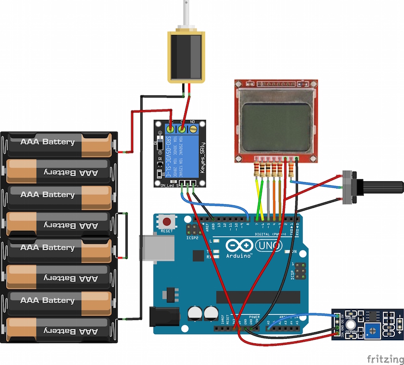
Circuit Diagram
The Nokia 5110 LCD operates on 3.3V, if we will connect it directly to the data pins on the Arduino then it will operate, but the lifetime of the Nokia 5110 LCD will decrease. So, if you want to use it for a longer span, then you will have to use the resistors as we used in our project.
To connect the Nokia 5110 LCD with the Arduino, make the connections for the Nokia 5110 LCD with the Arduino as follows:
- Connect pin 1 on the Nokia 5110 LCD which is the reset Pin to pin 6 on the Arduino through the 10K resistor.
- Connect pin 2 on the Nokia 5110 LCD which is the chip select pin to pin 7 on the Arduino through the 1K resistor.
- Connect pin 3 on the Nokia 5110 LCD which is the data or command pin to the pin 5 on the Arduino through the 10K resistor.
- Connect pin 4 on the Nokia 5110 LCD which is the data input pin to the pin 4 on the Arduino through the 10K resistor.
- Connect pin 5 on the Nokia 5110 LCD which is the clock pin to pin 3 on the Arduino through the 10K resistor.
- Connect pin 6 on the Nokia 5110 LCD which is the VCC pin to 3.3V pin on the Arduino.
- Connect pin 7 on the Nokia 5110 LCD which is the LED pin to the middle pin on the 1k potentiometer through the 330 ohm resistor and connect the other two pins to the VCC and the ground.
- Connect pin 8 on the Nokia 5110 LCD which is the ground pin to the GND on the Arduino.
The potentiometer used here is for increasing or decreasing the backlight of the LCD. If you want full backlight, then you can connect it directly to 5V. If you want no backlight, then connect it to ground.
After that, connect the relay module with the Arduino as follows:
- Connect the VCC pin on the relay to 5V on the Arduino.
- Connect the ground pin on the relay to GND on the Arduino.
- Connect the IN pin to pin 8 on the Arduino.
On the other side of the relay, connect the positive end of the battery to NC on the relay and C on the relay to the positive on the solenoid Valve. Then connect the negative on the battery to the negative on the solenoid valve.
Last, connect the FC-28 soil moisture sensor to the Arduino as follows:
- Connect the VCC pin on the FC-28 to the 5V pin on the Arduino.
- Connect the GND pin on the FC-28 to the GND pin on the Arduino.
- Connect the A0 pin on the FC- A0 on the Arduino.
How Does the Arduino Automatic Irrigation Sensor Work?
The soil moisture sensor will sense the moisture present in the soil and will give the output to the Arduino. The output of the sensor will be from 0-1023. The moisture is measured in percentage; therefore we will map these values as 0-100.
Whenever the moisture value is lower than value we have set in our code as the threshold value, the relay will operate and the valve will open. Whenever the moisture value is lower than this threshold value, then the relay will stop to operate and the valve will close.
Arduino Code
#include <PCD8544.h>

PCD8544 lcd;

int sensor_pin = A0 ;

int output_value ;

int valve_pin = 8 ;

void setup ( ) {

     lcd.begin (84, 48);

   lcd.print ("Reading From the Sensor ... " );

   pinMode (valve_pin, OUTPUT);

   delay (2000);

 }


void loop ( ) {

  output_value = analogRead (sensor_pin);

  output_value = map (output_value , 1023 , 0 , 0 , 100);

  lcd.clear ( );

  lcd.setCursor (0, 0);

  lcd.print (" Moisture = ");

  lcd.print (output_value);

  lcd.setCursor (0, 1);

  if (output_value < 40)

  {

  lcd.print (" Valve: ON ");

  digitalWrite (valve_pin , LOW);    //Relay operates on opposite signal

  delay (1000);

   }

  else

   {

    lcd.print (" Valve: OFF ");

  digitalWrite (valve_pin , HIGH);    //Relay operates on opposite signal

  delay (1000);

   }

  delay(1000);

  }
Code Explanation
First, we included the library for Nokia 5110 LCD and declared a variable named ‘lcd’ for the Nokia 5110 LCD library functions. Then we initialized different variables to read from the sensors and to turn the valve ON or OFF.
#include <PCD8544.h>

PCD8544 lcd;

int sensor_pin = A0 ;

int output_value ;

int valve_pin = 8 ;
In the loop function, we first get the readings from theFC-28 soil moisture sensor and store these readings in the ‘output_value’ variable. The output values of the sensor will be from 0 to 1023 but we need the moisture value which is in percentage, so we will map the output values of the sensor from 1023-0 as 0-100.
output_value = analogRead (sensor_pin);

 output_value = map (output_value , 1023 , 0 , 0 , 100);
Then we will print these values on the Nokia 5110 LCD and our system will turn the valve on or off according to it. If the moisture value is lower than 40, then we will make the valve pin low which will turn on the valve. If the moisture value is higher than 40, then we will make the valve pin high which will turn off the valve.
lcd.print (" Moisture = ");

  lcd.print (output_value);

  lcd.setCursor (0, 1);

  if (output_value < 40)

  {

  lcd.print (" Valve: ON ");

  digitalWrite (valve_pin , LOW);  //Relay operates on opposite signal

  delay (1000);

   }

  else

   {

    lcd.print (" Valve: OFF ");

  digitalWrite (valve_pin , HIGH);  //Relay operates on opposite signal