Part three in this series on how to build a mechanical television provides the schematics for circuit construction.
Editor's Note: This is part of a several part project by Vincent Portet. If you would like to see a specific chapter, refer to the table of contents below.
Mechanical Television Schematics
Now that we've covered the overview and chosen components, let's dive into circuit diagrams! If you need any clarification on a circuit, be sure to take a look at the
original project (PDF).
Synchronization and Luminance/Green Extractor
(“LUMA OUT” can go through the “gamma correction” circuit to improve picture crispness in B/W. But this is not mandatory)
LED Power Stages
This is the only part requiring an inductor (but with low constraints on characteristics: L > 100uH, I > 0,8A). (If not sure about the possible inductor value you may have in your salvaged component stocks, just test in this circuit: After having mounted the inductor and started the circuit, load the regulator with a 6.8 ohms 5W resistor and check that the BD136 stays at a temperature allowing to touch it permanently. If not, the inductance is too low. If the inductor is getting hot, it is rated for a too small current).
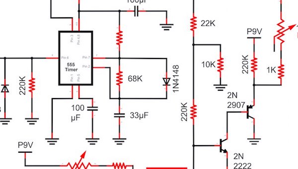
Motor Driving – Control Circuit
This circuit receives the extracted synchronization (like does the color decoder) and handles the optical sensor for issuing a control signal “CTRL” (polarity modulated pulses) which is connected to the power driver. The NE555 has a monostable time constant set just slightly longer than a 60-line synchronization pulse interval, so that divides the frequency by 2 in this case. In the case of a 30-line video, this division does not happen but in all cases, the output duty cycle is within [40%-60%].
Motor Driving – Power Circuit
The free-run speed adjustment and the vertical synchronization push button are visible here. P8 is used only during the tuning stage.
SECAM-like Color Decoder
This is the only part using a programmable component (code will be supplied in a later chapter): A common Microchip PIC16F819 micro-controller used to handle carrier synchronous demodulation (by synchronous sampling) as well as acting as the delay line required for SECAM (color alternated transmission, but here in AM). The frequency of the color carrier to be demodulated is the half of the WAV sampling rate (maximum possible frequency), so. 24KHz. The color pixel resolution is then the half of the green/white pixel resolution, while the same factor 2 applies for lines (due to color alternation). Therefore we can say that we use “quarter pixels” for color as it is usually done in high-resolution video.
Stay tuned for the next chapter, we will tackle applying color systems, circuit testing, and software. If you can't wait, check out the original project here (PDF).