Make a simple punch card reader, which uses punched card or paper to store data.
Modern technology allows us to store gigabytes of information in memory cards that are no bigger than a penny. However, computer users in the past were not so fortunate and had to rely on more primitive methods for storing data. One popular method for permanently storing data was the use of punched card or paper which could be used to store programs or personal information. Incredibly, this technology was used as late as the 90’s and provides a very reliable method for data storage. In this project, we will build a simple punch card reader that be used to read from DIY punched cards!
Punch Card Reader Circuit
How Does the Punch Card Reader Work?
The circuit uses a microcontroller to read parallel data from the card reader and then stream this data over a UART connection (via TX). This serial connection can be connected to either a computer or other microcontroller so that system can read the punched card. The microcontroller also has a UART receive line to receive the “read character” instruction which starts the motor when executed. The motor stays on until a new clock signal is generated by the card reader. At this point, the microcontroller reads the byte from the card reader and then transmits that over UART.
The card reader consists of 9 paper clips pushed into a conductive base plate. It is important that the paper clips are not under too much stress, otherwise, the paper clips will permanently deform and lose their flexibility. For a long-lasting device, the baseplate should be made from a corrosive material such as stainless steel. In this example, copper is being used for demonstration only.
The motor circuit is a BJT transistor with a protection diode to prevent EMF spikes in the motor from damaging the transistor. The power regulation circuitry (U1) also has two protection diodes where the Schottky diode (D2) provides reverse power protection while the 1N4148 diode (D1) provides EMF spike protection for the regulator.
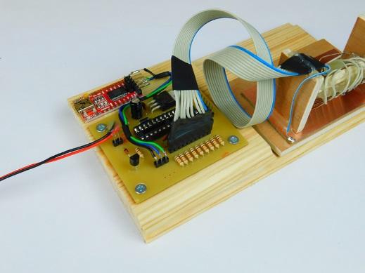
Constructing Your Punch Card Reader
The paper tape reader itself consists of 9 paper clips that are cut and bent as to provide a spring-like action. Normally, they make contact with the base copper plate shown in the picture but this contact is broke when paper is fed through. This contact is remade when a hole in the paper appears and this pulls that paper clip to ground (recording a 0).
Paper clip bending and cutting
Eight paper clips as data lines
One paper clip on the back as the clock line
Tape reader from the front
The main circuit is mounted next to the tape reader with fours screws and a piece of wood. The wood helps to prevent the screws from going through the base and this piece of wood is also glued to the main base. Next to the main circuit is an FTDI serial to USB to provide USB output to a serial terminal (mainly for debugging). The motor enable output can be used to connect a motor to the paper tape reader to automatically pull the tape in when a command is transmitted to the paper tape reader via UART.
The completed tape reader
Tape reader from the side