This flame alarm, which functions like a typical smoke alarm, can detect a smokeless flame or oil fire.
Smoke detectors are great for detecting smoke, and carbon monoxide detectors are great for detecting carbon monoxide. But what about a smokeless flame? Or what about an oil fire? In this DIY Hacking project, we will make a flame alarm that functions just like a typical commercial smoke alarm!
Schematic
How the Flame Detector Works
The goal of this project is to make an alarm that signals when a flame is present. This is achieved with three main components:
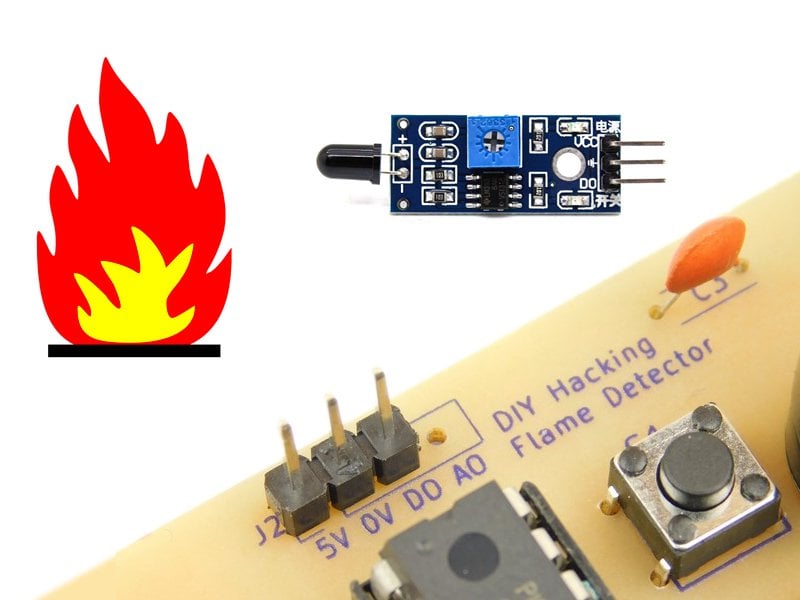
- A flame detector module
- The controller circuit
- Firmware coded into the main controller
The flame detector module is a simple op amp comparator with an IR diode. Flames emit large quantities of IR radiation, and this radiation can be detected with an IR diode. The module compares the voltage drop over an IR diode to a reference voltage and outputs a signal, depending which one is greater. When a flame is detected, the output switches low, and when a flame is not detected, the output switches high. The potentiometer on the module can be used to adjust the sensitivity so daylight can't trip the system.
The controller circuit is simple, with the core of the circuit being the PIC16F819. A switch is used for resetting/testing, a buzzer for alerting those nearby, one green LED to indicate that the module is functioning correctly, and a red LED for indicating that the detector is taking readings from the flame module. The circuit also has a small power management sub-circuit, which uses a 7805 IC in an SOT-89 package for power regulation.
The real magic in this project lies in the firmware on the PIC16F819. The code itself is written in XC8 and is only 100 lines long, with many of the lines being empty space, braces, or comments. When executed, the PIC goes through setup procedures, including setting the TRIS bits, disabling the ADC, and configuring the oscillator. Once done, the PIC enters an infinite loop that probes the module to see if the output is low or high. If low, then a flame has been detected and the alarm routine is triggered. This routine makes the buzzer beep indefinitely until the test button has been pressed and held. If no flame has been detected, the program makes the red LED blink to indicate that measurements are being taken, and also looks to see if the test button has been pressed. If it has, the buzzer is sounded to prove that the unit (or at least the main circuit) is, in fact, working.
Construction
This project can be built using many different circuit construction techniques, including stripboard, breadboard, matrix board, and PCB. However, if not using a PCB, the 7805 you use should be a through-hole type, as the surface mount 7805 is very small and only suitable for PCBs. This project is the first project to use the new PCB production line I have set up for future projects, and these PCBs include a neat silkscreen and soldermask, which makes building the projects a lot easier. A CNC is still used to drill the holes, but the traces are now done with ferric chloride and photoresist.
Downloadable Files
Related Articles