Learn about the Modbus protocol and how to access it using a simple RS485 HAT for your future Raspberry Pi projects!
I’ve been playing around with the Modbus communication protocol, considering it as an alternative communication system for my homegrown smarthome devices. So far, I’ve connected these devices via Meterbus.
I built a thermometer and alarm system for the freezer and the fridge in the basement with a very simple Arduino-based Modbus master with very limited hardware and only hardcoded mapping of client registers. However, I soon after discovered ESP8266 modules and I switched more or less completely to connecting homegrown devices via Wi-Fi.
Recently, I found a lot of interesting, cheap Modbus-connected devices (Remote IO, PT100/PT1000 converters, etc.) on eBay and I became curious about working on a more advanced, configurable Modbus master again.
With some Googling, I found a few off-the-shelf Modbus RPi HATs on eBay and Amazon. Most of them came as open source hardware, so I was able to compare the particular schematics with the related data sheets and application notes for the central RS485 transceiver. In this article, I’ll walk you through how I created my own RS485 HAT for a Raspberry Pi based on the Modbus communication protocol.
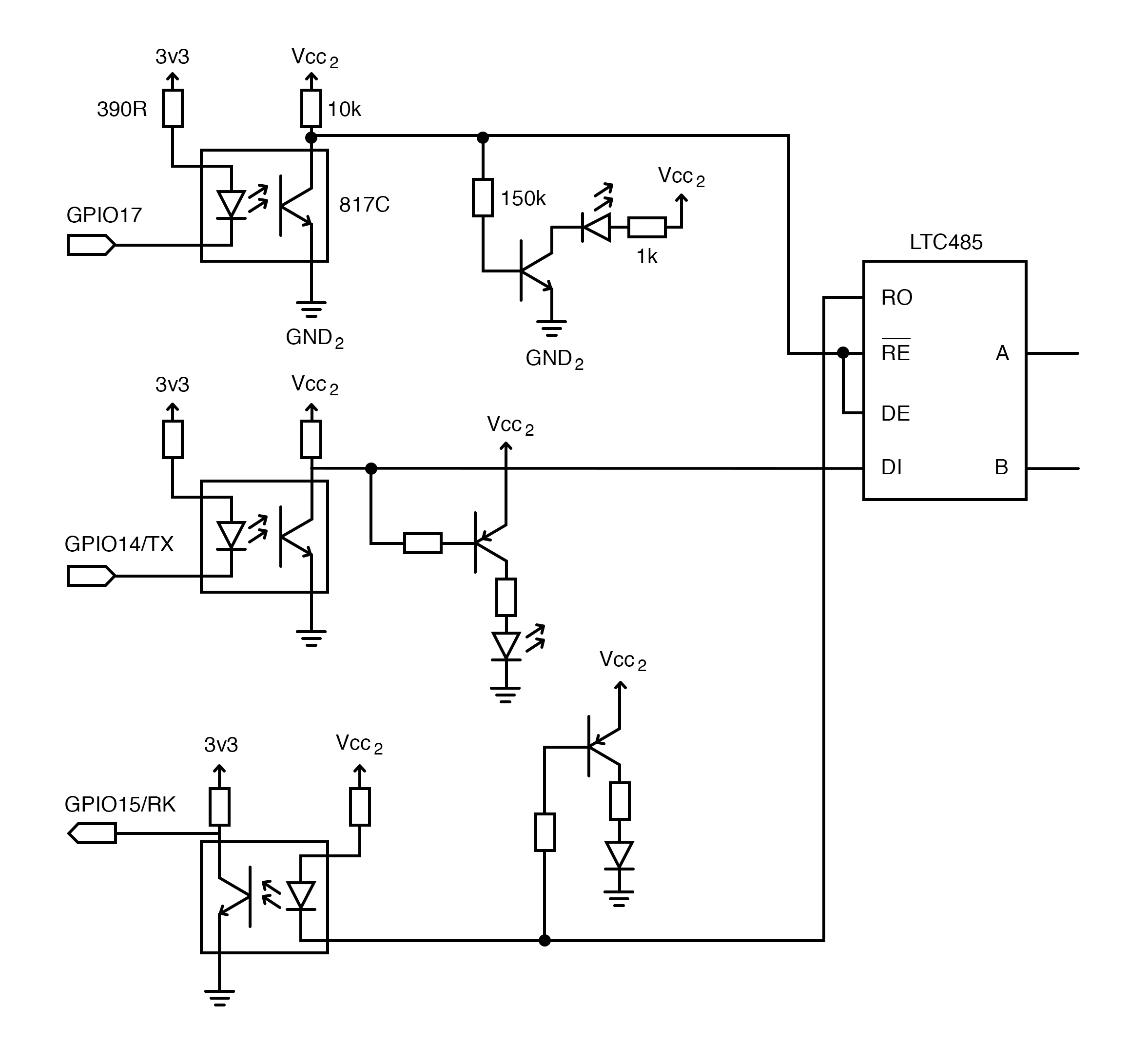
Digital side of the RS485 transceiver including RPi pin assignments
Designing the Hardware
The hardware was quite straightforward. I needed three things to happen:
- Isolation of data signals with optocouplers.
- Isolation of the supply power for the transceiver with a DC/DC converter.
- Protection of the bus-side data lines with resistors and suppressor diodes.
I found a lot of hardware configurability with these off-the-shelf hats, which I don’t necessarily like or need. Moreover, the handling of data-enabled signal did not match my ideas — I like to control the signal (which is very important for RS485 communication) directly with the controller using software, ideally via the serial driver in the kernel.
Since my idea was to use Python to implement the software for this project I looked into the pySerial module. It actually supports a dedicated RS485 mode, which drives the RTS pin (GPIO 17 at the RPi) while sending data over the TX pin.
So, I used the RS485 mode of the pySerial module and implemented a very small test script to receive some data and send out the echo. This test script worked well.
import serial.rs485
ser=serial.rs485.RS485(port='/dev/ttyAMA0',baudrate=2400)
ser.rs485_mode = serial.rs485.RS485Settings(False,True)
ser.write('a test'.encode('utf-8'))

while True:
    c = ser.read(1)
    ser.write(c)
    print(c, end='')
First working RS485 communication, RX in blue, TX in yellow, DE (data enable) in purple
In blue we see the RX signal, in yellow the TX signal and in purple the DE (data enable) signal: DE is enabled during the TX phase, however, it stays active for quite awhile. Moreover, when running this test a couple of times, the delay of switching off the DE signal after finishing transmission varies a lot.
Moving From Simple RS485 to Modbus Communication
The next step was to move on from simple RS485 to actual Modbus communication. I connected a Modbus-connected power meter, which I have from my earlier experiments, to the setup.
Device with connected oscilloscope probes
What I found next with another quite simple test script using the PyModbus module was a bit disappointing.
from pymodbus.client.sync import ModbusSerialClient
import serial.rs485

ser=serial.rs485.RS485(port='/dev/ttyAMA0',baudrate=1200)
ser.rs485_mode = serial.rs485.RS485Settings(rts_level_for_tx=False,
                                            rts_level_for_rx=True,
                                            delay_before_tx=0.0,
                                            delay_before_rx=-0.0)

client = ModbusSerialClient(method='rtu')
client.socket = ser
client.connect()
result = client.read_holding_registers(address=0x2000, count=2,
                                       unit=1)
print(result)
print(result.registers)
client.close()
Sometimes, the communication worked and sometimes it did not. The reason for this inconsistency was found rather quickly using the oscilloscope.
Working Modbus communication, TX in yellow, RX in blue, DE in purple. Note falling slope of DE before RX starts
In the next figure, the DE signal (in purple) is disabled before the client starts sending its response.
The oscilloscope shows that the Modbus communication isn’t working. Note overlap between DE and RX
Here, it still does not work. The long hold time of about 18ms of the DE (transmitter enabled, RTS line) became a problem. The response of the device would already start when the transmitter of the master was still enabled. Thus, the receiver of the master was still disabled.
I did a couple of experiments around deriving from the RS485 class of pySerial and moving the time critical code (disabling the transmitter after the transmit) into C code failed. It wasn't faster at all. It became obvious that the system call tcdrain, which waits for all octets in the buffer to be transmitted, returned very late.
Finally, I found a solution, which was to get away from the RS485 mode in pySerial and, instead, use the line status register of the UART via a system call to see whether the transmit register was empty and switch the DE line of the transmitter no longer with the RTS functionality but directly using wiringPi. This significantly shortens the hold time of the DE signal after the completed transmission.
Experimenting With wiringPi
In an early experiment with this approach I used the bcm2835 library. However, I decided to get away from this library and use wiringPi for licensing reasons. The bcm2835 is under GPL (not even LGPL), but I wanted to use the more permissive MIT license for my own code which is not compatible.
import serial.rs485
import serial.serialutil
import ctypes

class RS485Ext(serial.rs485.RS485):
    def __init__(self, *args, **kwargs):
        super(RS485Ext, self).__init__(*args, **kwargs)
        self.writec = ctypes.cdll.LoadLibrary('writec.so')
        r = self.writec.init()

    def write(self, b):
        d = serial.serialutil.to_bytes(b)
        r = self.writec.writec(self.fileno(), d, len(d))
        return r


#include <unistd.h>
#include <sys/ioctl.h>
#include <stdint.h>
#include <wiringPi.h>

const uint8_t DE_PIN = 0;

int init() {
  wiringPiSetup();
  pinMode(DE_PIN, OUTPUT);
  digitalWrite(DE_PIN, LOW);
}

ssize_t writec(int fd, char *buf, size_t count) {
  digitalWrite(DE_PIN, HIGH);
  ssize_t r = write(fd, buf, count);
  uint8_t lsr;
  do {
    int r = ioctl(fd, TIOCSERGETLSR, &lsr);
  } while (!(lsr & TIOCSER_TEMT));
  digitalWrite(DE_PIN, LOW);
  return r;
}
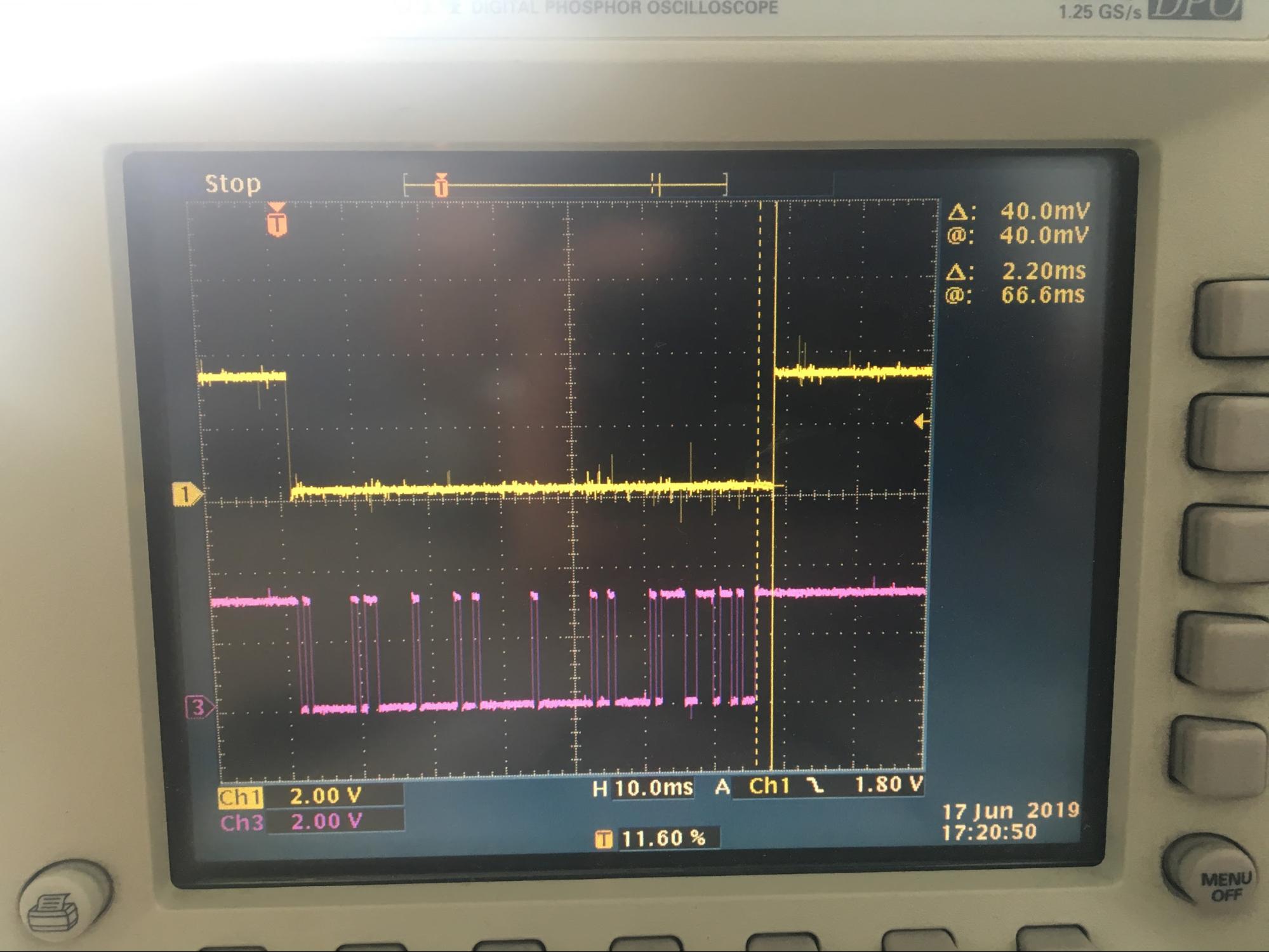
Photo from a different oscilloscope. DE in yellow, TX in purple. Note the significantly shortened hold time of DE, measured with cursors
From about 20ms with a lot variance down to 2.2ms! That’s good.
Now, another try with real Modbus communication was required, again with the power meter.
Again TX in yellow, RX in blue, DE in purple. Note the shortened DE hold time and the dirty RX signal
The transmitter was disabled and the receiver was enabled a good while (more than 20ms) before the response of the Modbus client started. However, I still saw a significant error rate and the RX signal is obviously dirty. Moreover, I experienced that, as soon as I connect the termination resistor of 120 Ohms, nothing was received any more. Strange.
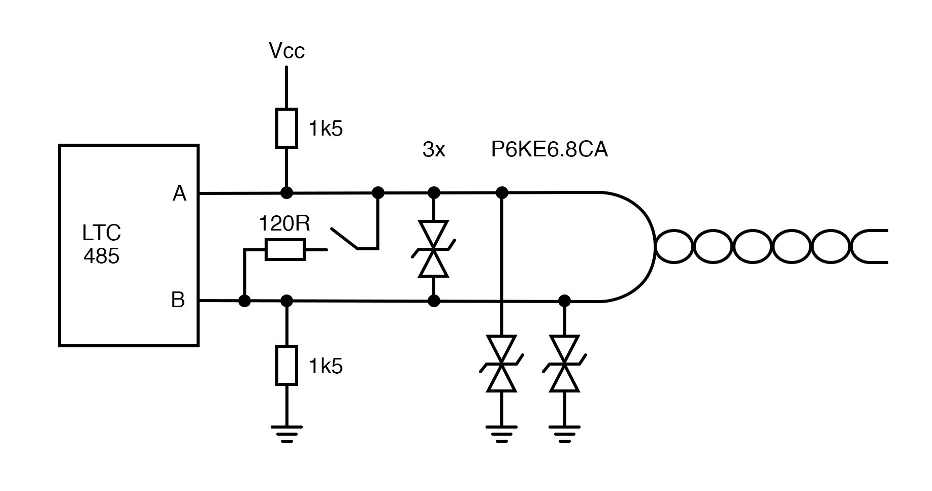
Continuing to read the application note AN-960 (PDF) from Analog Devices gave the required hint to solve this issue: when all transmitters on the bus are disabled, the lines are floating. And since only +/- 200mV decide it’s low and high, the receiver might actually receive a lot of noise. The recommendation from the app note, under the section “Fail safe biasing” is to pull the A line of the bus to Vcc (of course from the isolated side of the transceiver) and the B line to Gnd.
Improved line interface according to application note from Analog Devices
Putting the resistors into this setup solved the issue. The RX signal became very clean and the termination resistor was no longer a problem.
Modbus communication with improved line interface. Note the clean RX signal in blue
Implementing More Test Scripts
The next step was to implement a couple more test scripts. With this script, I continuously poll data from two Modbus clients (from the aforementioned power meter and homegrown fridge/freezer thermometer), which now works perfectly.
After all this preparatory work, I’m currently working on an application to be run on the Raspberry Pi. It will contain a text-based configuration interface to configure Modbus registers to be considered at runtime. It will publish changes from read Modbus registers via MQTT and it will write commands received via MQTT to Modbus registers.
The whole project lives in one of my Gitlab projects. Feel free to connect if you are interested in the progress and if you like to use this hardware and software in your own project — which you freely can do, it’s all under an open source license.
The final device mounted on the RPi