Learn how to use the littleBits Bluetooth module with a Raspberry Pi Zero WH to help you with your IoT projects!
Small colorful electronic modules called littleBits allow a variety of gadgets and devices — like wearables, robots, interactive remote controllers, and physical games — to be created by makers, educators, and hobbyists.
littleBits has the capability to wirelessly interact with the Raspberry Pi Zero W thereby allowing IoT devices to be built. This tutorial will show you how to build a basic wireless controller. To get started, you will need a few off the shelf electronic components and a littleBits Bluetooth Low Energy (BLE) module to control a Pi Zero W.
Required Hardware
Transistor Relay Driver Circuit
To control the Pi Zero W, an electrical interface circuit is required. Traditionally, controlling a Pi Zero to generate text on the screen or to operate a LED a simple electric switch is used.
Although using an electric switch is an effective method to operate a Pi Zero, this electrical approach lacks the ability for wireless operation and control. Luckily, another method to operate the Pi Zero and allow wireless control is possible with a transistor relay driver circuit.
A transistor relay driver allows control of high current circuits using an external switching contact. Figure 1a illustrates a typical transistor relay driver circuit. As shown in Figure 1b, closing the electric switch will allow the transistor (Q1) to turn on.
Figure 1a. A typical transistor relay driver circuit. The electromechanical relay’s contacts are open thereby turning off the DC motor
Figure 1b. The electromechanical relay’s contacts are closed allowing the dc motor to turn on
With the transistor turned on, the electromechanical relay’s coil is electrically energized. This energized electromechanical relay closes its contacts using a magnetic field. The electromechanical relay’s contact provides a control signal to the appropriate GPIO of the Pi Zero W.
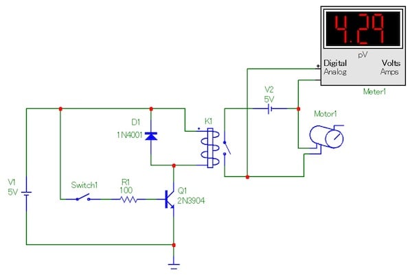
To show another perspective of a transistor relay driver circuit, a TinkerCAD model illustrates the operation of the electromechanical relay. Figure 2a demonstrates an open relay contact displayed by the ohmmeter’s infinite resistance reading.
Figure 2a. The ohmmeter’s reading displaying an open electromechanical relay contact
Pressing the tactile switch energizes the electromechanical relay’s coil switching the contacts closed. The ohmmeter displays a continuity value of zero ohms.
Figure 2b. The ohmmeter’s reading displaying a closed electromechanical relay contact
With a good understanding of the operation of a transistor relay driver, the next step is wiring the transistor relay driver to the Pi Zero W.
Connecting the Pi Zero W to the littleBits module
The final construction of controlling a Pi Zero W with a littleBits module is the wiring of the transistor relay driver circuit to the small SBC. Figure 3 shows the block diagram of the wireless interface to operate a Pi Zero W. The tactile switch is used to test the transistor relay driver circuit prior to wirelessly controlling the Pi Zero W with a littleBits BLE bit and mobile device.
Figure 3. The system block diagram of the littleBits BLE controller
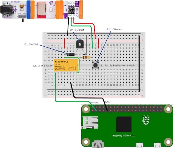
Use the electrical wiring diagram shown in Figure 4 to build the littleBits BLE controller. The placement of the electronic components should be as close to the wiring diagram as possible. To assist you in the wiring of the transistor relay driver circuit, an electrical pinout of the Pi Zero W is provided in Figure 5.
Figure 4. The electrical wiring diagram of the littleBits BLE controller
Figure 5. Pi Zero W GPIO Pinout
With the transistor relay driver circuit wired and tested on the solderless breadboard, you will build the code using EduBlocks. The basic code for testing littleBits BLE control interface is shown in Figure 6.
Figure 6. The EduBlocks blockly code for testing the littleBits BLE controller
You can also code the software in the Python programming language as shown in Figure 7.
Figure 7. The equivalent Python code for the littleBits BLE controller
littleBits Gizmos and Gadgets App
To operate the BLE controller you will need the littleBits’ Gizmos and Gadgets app installed on an iOS or Android mobile device. The mobile device app allows a variety of controls such as a slider or button to operate the Pi Zero W. Also, the mobile device’s accelerometer by way of a shake motion can activate the Pi Zero W.
Figure 8. The Gizmos and Gadget app is compatible with iOS and Android mobile devices
After you have installed the littleBits app on your mobile device, power the BLE controller interface with a 9V battery. Open Gizmos and Gadgets and pair the mobile device by selecting the wBLE icon. Select the button control and touch it with your finger. You should see the BLE message displayed on your HDMI monitor screen. Releasing the button will display the Waiting BLE message
Figure 9. Pressing the Gizmos and Gadgets button control displays the BLE message on a HDMI monitor
You now have a wireless controller to explore the world of IoT. There is a multitude of awesome devices you can operate with your BLE controller. Happy IoT exploring!