Learn how to build a voltage-controlled power supply and connect it to RIOTOUS to create an IoT-controlled power supply.
Power supplies are really useful pieces of test equipment, but most, if not all, are manually controlled. In this Maker Pro project we will combine RIOTOUS with a voltage-controlled power supply to create an IoT-controlled power supply.
Schematic
How It Works: Hardware
The hardware for the RIOTOUS power supply has two main aspects:
- A variable linear regulator based around the LM317
- A PWM generator that sets the LM317 output voltage
The LM317 is a linear regulator that has three pins: VIN, VOUT, and ADJ. The VIN and VOUT pins are used for the voltage input and voltage output, respectively, while the ADJ pin, which stands for “adjust”, is used to adjust the voltage output.
If the circuit below is used with the LM317, the output voltage is given in the equation below.
However, as it turns out, if the feedback resistor R1 is left in its place and R2 is replaced with a voltage source, the output voltage of the LM317 is approximately 1.3V higher than the input voltage. Therefore, if we can create a variable voltage from the PIC16F1825, we should be able to control the LM317 output. The PIC16F1825 has a DAC that can be used to produce a variable voltage source, but this is a 5-bit DAC, so there are only 32 possible voltages. Instead, we will use a PWM source that is smoothed to create a voltage source whose magnitude is controlled by the duty cycle of the PWM signal.
There is one issue with using the PWM signal from the PIC16F1825, which is that the maximum output voltage of the PWM signal will be the supply voltage of the PIC. Therefore, the maximum voltage that we can get out of the LM317 will be 3.3V + 1.3V = 4.6V. To get around this, use an op-amp amplifier, which multiplies the output voltage of the PWM signal by 10, which allows a voltage range between 1.3V and 34.7V.
How It Works: Software
The client side (the RIOTOUS-powered PIC) starts by configuring IO ports, the internal oscillator, and the RIOTOUS framework. When this is done, interrupts are enabled, and then the microcontroller attempts to connect to the specified Wi-Fi network. Once connected, the system then tries to connect to the server, and once a successful connection has been established, the main while loop is executed.
In this loop, the code first checks to see if the server has sent data to adjust the duty cycle, and if there is, the incoming duty cycle string is converted into an integer and then transferred to the duty cycle variable. Once the incoming data has been handled, the PIC then runs the PWN generation code. While the PIC does have an onboard PWM module, it caused a lot of headache to try and get operational (especially when CCP1 uses the RX pin, which is needed for the ESP8266). Therefore, the PWM signal was generated in code and is very simple to implement.
On each iteration of the main loop, a counter variable is incremented, and this value is compared to the period variable. If the timer has exceeded the period variable, then the timer is reset. If the timer value is lower than the duty cycle value, then the PIC sets the PWM pin to 1 else it sets it to 0.
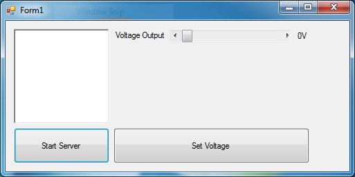
The server program is written using VB.net and consists of a simple form application with a button to enable the server, a button to set the voltage, and a slider that allows the user to choose the desired output voltage. Upon loading, the form application initializes a RIOTOUS server, and when the button Start Server is clicked, the RIOTOUS server is started on the IP address of the machine using port 333. Included in the form is a timer that acts as a program ticker that checks for RIOTOUS events, but since our client does not send data to the server, this ticker is not needed. When the horizontal bar is adjusted, the “voltage label” is changed to show the voltage that the horizontal bar represents, and when the Set Voltage button is pressed, then the server sends the new duty cycle to the PIC.
Construction
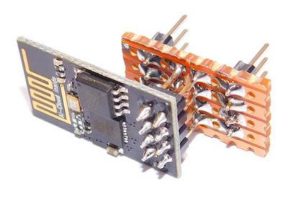
This project can be constructed using many different techniques including stripboard, breadboard, matrix board, and custom PCB. For this project, I opted to make the circuit using breadboard, but this did provide a challenge or two. First, the project will not fit on one small breadboard, so two needed to be connected together. Second, the ESP-01 is not breadboard-friendly. Therefore, an adaptor was needed to allow the ESP-01 to work with breadboards, and this was achieved using a small piece of stripboard and some headers.
While this project does not provide other features needed in a power supply, such as rectification and an output display, it shows a proof of concept that RIOTOUS and the ESP8266 can be used to make just about anything internet controlled. If other components are added, including a transformer, mains connection, large smoothing capacitors, and various other power components, then this project could quickly become a full-featured IoT power supply!