This wireless power logger measures voltage, current, and power draw with the RIOTOUS V0.2 and a VB.net-powered program.
Power logging can be very useful in situations where the average power draw of a circuit needs to be determined. In this project, we will create a wireless power logger that can be used to measure voltage, current, and power draw, which streams its data to a VB.net-powered program using RIOTOUS V0.2.
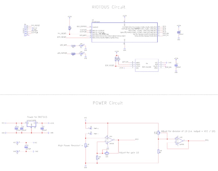
Schematic
The Power Logger Circuit
The RIOTOUS-based circuit consists of a microcontroller (the PIC16F1825), an ESP-01 module for Wi-Fi connectivity, analog circuitry for recording voltage and current (U2), and basic power regulation (U1). To record how much power is consumed by a device, two variables need to be obtained: voltage drop across the device, and the current flowing through that device. Voltage draw is very easy to determine since the external device is being powered by the VCC rail, so an analog measurement of this can be taken directly by the microcontroller using an analog pin.
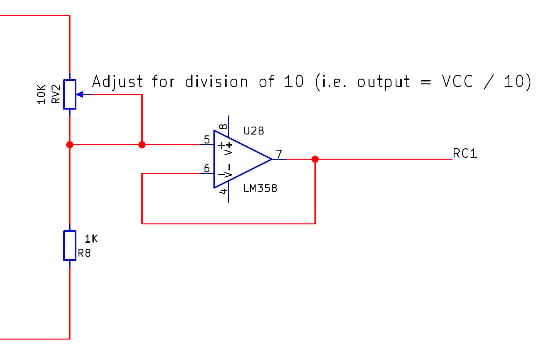
However, since VCC will be larger than the 3.3V supply that the PIC uses, the VCC voltage is first fed into a potential divider (RV2 and R8), which divides the voltage by 10. This divided voltage is then buffered by a unity gain amplifier (U2B), which is then fed into one of the PICs analog-digital inputs. By doing this, we can measure VCC values up to 33V (which is far beyond what the AMS1117 can handle anyway).
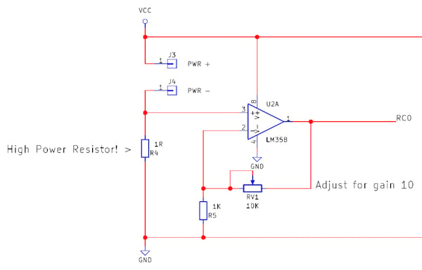
The second parameter we need to record is current, which is slightly trickier to measure. In our circuit, we use a sense resistor (R4), which is essentially a resistor that sits in series with the device under test. Because the resistor is in series, it will have a voltage drop across it, and the voltage drop will be proportional to the current flowing through it (thanks to V = IR). Rearranging this formula to make I the subject reveals...
Because the resistor and device are in series, the current flowing through the sense resistor must be the same as the current that flows through the device (thanks to Kirchhoff’s law). Therefore, we can determine the current flow through the device by dividing the voltage drop across the sense resistor by its resistance (which is known). Before the voltage drop is measured by the PIC, it is first multiplied by 10 with the use of U2A. This makes it easier to detect smaller currents, but at a cost of limiting the maximum current we can measure.
The Circuit Code
The firmware on the PIC16F1825 uses the RIOTOUS framework to handle the ESP8266 as well as incoming and outgoing data. On start up, the logger tries to connect to the specified Wi-Fi network and then connect to the server (which is our power logger program written in VB.net). Once a connection has been established, the PIC waits until a “start logging” command is sent. When this command has been sent, the PIC starts taking periodic readings of both voltages (VCC and the voltage drop across the resistor). Upon taking readings, the supply value is multiplied by the sense resistor voltage divided by its resistance to give the power consumption. This value is then sent to the server program for logging on a chart using a VB.net form application.
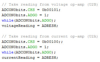
Here's the code that reads the ADC peripheral to measure the current and voltage:
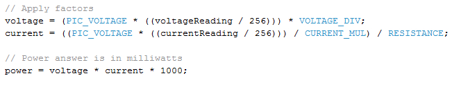
Next, we add in the calculation code that determines the power consumption:
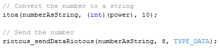
Finally, we insert the code that converts the result to a string and sends it to the server:
Server Code
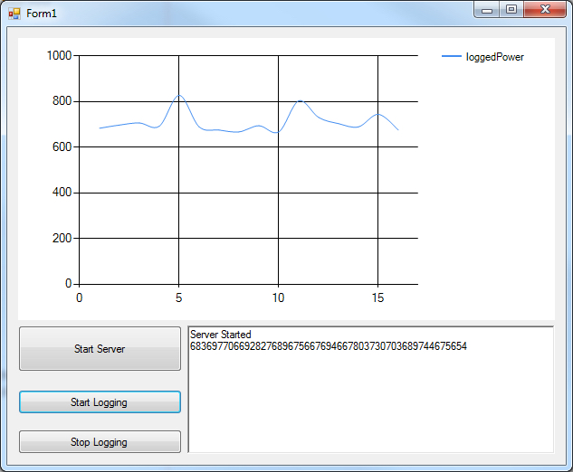
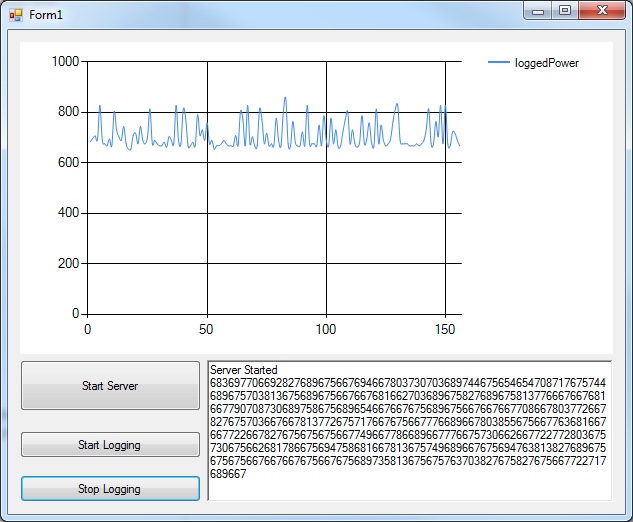
The server side is the application that uses RIOTOUS to establish a RIOTOUS server that our logger can connect to. Then, as readings are streamed in the VB.net form, application plots the data onto a chart to show the rolling power consumption.
The logger having just started
The logger after a minute
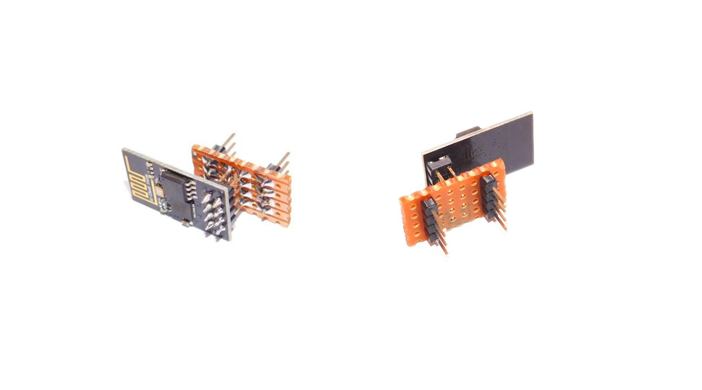
Construction
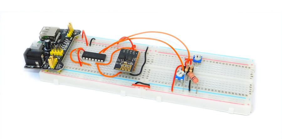
This circuit can be built using many different circuit board techniques including stripboard, breadboard, and even a PCB. My first attempt at this project was using a PCB, but due to a daft error that I had made (using the programming ports as my analog-read channels), I had to redesign the project. However, instead of making another PCB, I opted to use a breadboard, which provided a challenge!
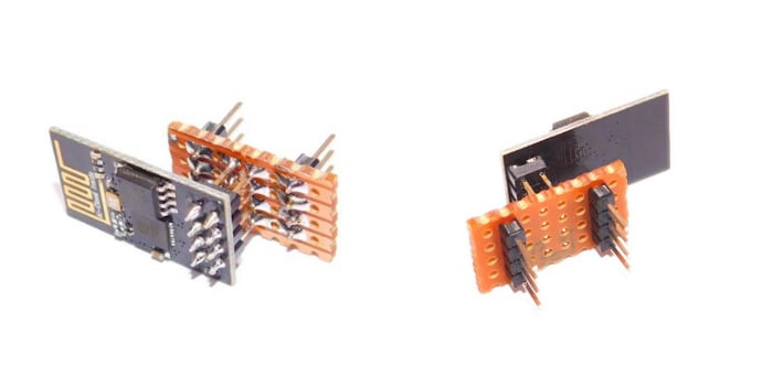
The ESP-01 module uses 0.1” headers, which is helpful for hobbyists, but the headers have two rows, which means it cannot be used on a breadboard. Therefore, I had to use a piece of stripboard to create an adaptor that would allow it to work with a breadboard.