Protect electronic circuits from incorrect power connections with a low-loss MOSFET solution.
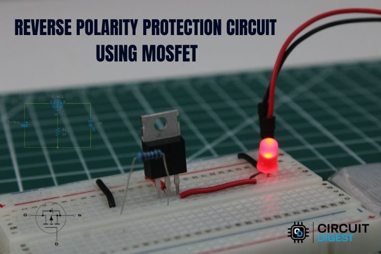
MOSFET Reverse Polarity Protection Circuit
Reverse polarity is one of the most common mistakes made during electronics prototyping and deployment. Accidentally connecting a power supply or battery backwards can instantly damage microcontrollers, sensors, motor drivers, and other sensitive components.
Fortunately, a simple protection circuit can prevent this problem entirely. In this project, we will build a reverse polarity protection circuit using a P-channel MOSFET that allows current to flow only when the power supply is connected correctly. Compared to traditional diode protection, this method offers much lower voltage drop, improved efficiency, and minimal heat generation.
This guide explains how the circuit works, how to build it, and how to select the right components for reliable protection.
Understanding Reverse Polarity
Reverse polarity occurs when the positive and negative terminals of a power supply are accidentally swapped. This can happen due to:
- Incorrect battery installation
- Miswired connectors
- Wrong polarity power adapters
- Human error during testing or assembly
Without protection, reverse polarity can destroy integrated circuits, burn components, and in extreme cases cause overheating or fire hazards.
Adding a protection circuit at the power input stage ensures that your device remains safe even if the power supply is connected incorrectly.
Limitations of Diode-Based Protection
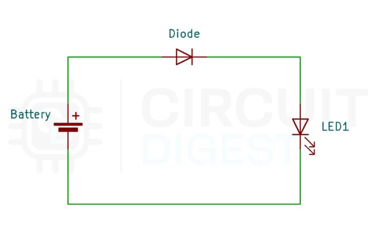
The simplest protection method uses a diode connected in series with the supply line. When the polarity is correct, the diode conducts and allows current to reach the circuit. If the polarity is reversed, the diode blocks the current and prevents damage.
Although effective, this approach has a drawback: the diode introduces a forward voltage drop, typically around 0.6–0.7 volts. This voltage loss reduces the available supply voltage and converts energy into heat. In battery-powered systems, this inefficiency can shorten battery life and reduce overall system performance.
To overcome these limitations, designers often use MOSFET-based protection circuits.
Components Required
To build a reverse polarity protection circuit using a MOSFET, only a few components are required:
- P-Channel MOSFET (for example, IRF9710)
- 1 kΩ resistor for gate biasing
- 1N4007 diode for additional protection
- DC power supply or battery
- Load device such as an LED, motor, or microcontroller
- Breadboard and connecting wires
These components create a compact and efficient protection stage for the input power line.
Circuit Design Using a P-Channel MOSFET
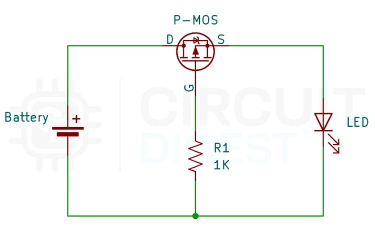
In this design, a P-channel MOSFET is placed in series with the positive supply line. The MOSFET acts as an electronically controlled switch that responds automatically to the polarity of the input voltage.
The source terminal of the MOSFET is connected to the positive terminal of the power supply. The drain terminal connects to the load, which then connects to ground. The gate is pulled down to ground through a resistor, creating the proper gate-to-source voltage required to control the device.
A protection diode may also be included in the gate path to prevent reverse voltage conditions that could damage the MOSFET.
This configuration ensures that the circuit only conducts power when the supply polarity is correct.
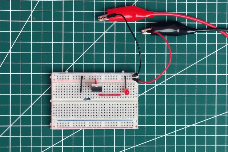
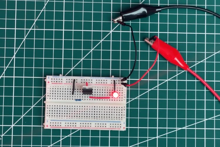
Step-by-Step Assembly
Begin by placing the P-channel MOSFET on the breadboard and identifying its source, gate, and drain pins from the datasheet.
Connect the source pin directly to the positive terminal of the input power supply. The drain pin should then connect to the positive input of the load.
Next, connect a 1 kΩ resistor between the gate and ground. This resistor acts as a pull-down resistor and ensures that the gate voltage remains lower than the source voltage when the supply is connected correctly.
Add a diode between the gate and ground if additional gate protection is desired. Finally, connect the load between the MOSFET drain and ground.
Once assembled, the circuit is ready to test with both correct and reversed power connections.
How the Circuit Works
The behavior of the circuit depends on the polarity of the input power supply.
When the power supply is connected correctly, the source of the MOSFET is at a positive voltage while the gate is pulled toward ground through the resistor. This creates a negative gate-to-source voltage, which turns the MOSFET on. When the MOSFET conducts, current flows through the device with very low resistance, powering the load efficiently.
If the power supply polarity is reversed, the voltage relationship between the gate and source changes. The gate-to-source voltage becomes positive, preventing the MOSFET from turning on. As a result, the current path is blocked and the load receives no power.
The internal body diode inside the MOSFET also helps ensure that reverse current cannot flow through the circuit.
Efficiency Advantage of MOSFET Protection
One of the biggest advantages of this design is its extremely low voltage drop.
For example, in a 12-volt system drawing 500 mA, a diode may drop around 0.7 V, wasting approximately 0.35 W as heat. In contrast, a MOSFET with a low drain-source resistance may drop only around 0.05 V, resulting in minimal power loss.
This dramatically improves efficiency and reduces heat generation, making the MOSFET approach ideal for battery-powered electronics and high-current applications.
Adding Zener Gate Protection
In higher-voltage systems, it is possible for the gate-to-source voltage of the MOSFET to exceed safe limits. Most MOSFETs have a maximum gate voltage rating, typically around ±20 V.
To prevent damage, a Zener diode can be added between the gate and source. This diode clamps the gate voltage to a safe value and protects the MOSFET from voltage spikes or high input voltages.
This improved version of the circuit is commonly used in automotive electronics and industrial equipment where supply voltages may fluctuate.
Choosing the Right MOSFET
Selecting the correct MOSFET is critical for reliable operation. When choosing a device, consider the following parameters:
The drain-source voltage rating should be higher than the maximum supply voltage, including any transient spikes. The current rating must exceed the maximum load current with sufficient safety margin.
The most important parameter is the drain-source on-resistance, commonly called RDS(on). A lower resistance reduces power loss and improves efficiency.
Finally, verify that the gate-to-source voltage rating is compatible with the intended operating voltage.
Applications
MOSFET-based reverse polarity protection circuits are widely used in many electronic systems.
Battery-powered devices benefit from improved efficiency and longer battery life. Microcontroller projects such as Arduino and ESP boards gain additional safety during development and testing.
IoT devices, smart sensors, and embedded electronics often incorporate this protection at the power input stage. Automotive electronics also use similar circuits to protect control modules from accidental reverse battery connections.
Even motor drivers and power modules can use this approach to safeguard their input stages.
Conclusion
Reverse polarity protection is a small design step that can save an entire project from catastrophic damage. While diode-based protection is simple, it wastes energy and introduces unwanted voltage loss.
Using a P-channel MOSFET provides a much more efficient alternative. The circuit automatically blocks reverse current, introduces almost no voltage drop, and generates minimal heat. With only a few inexpensive components, designers can add a robust protection stage to any electronic system.
Whether you are building a hobby prototype, an IoT device, or a commercial product, integrating MOSFET-based reverse polarity protection is a smart and reliable engineering practice.
Explore a wide collection of DIY electronic circuits and schematics on learn and build practical circuits with detailed explanations and diagrams.