Before we start with the circuit build, head over to the Arduino IDE.
Arduino Software
Open the Sketch ArduinoISP from the File, Examples and ArduinoISP menus:
- Verify and upload this sketch to your Arduino
The Arduino software does not natively support the ATtiny85 so we need to add support for it.
- from the File menu.
- ".
- Click OK!
ATTiny
- from the Tools, Board Menus
- from the list once the software has updated
Note that you will require an internet connection for the ATtiny board manager to download.
- Search for ATtiny, either manually scrolling down the list, or typing "attiny" in the filter field.
- Click Install the (Use the latest version).
Program Setup
Lets set up the program to use the Arduino as a programmer.
- from the Tools, Programmer Menus
- from the Tools, Board Menus
- from the Tools, Processor Menus
- Internal from the Tools, Clock Menu
The chip has 8 pins, to program the ATtiny85 we are interested only 6 of them MISO, MOSI, SCK, RESET, Ground, and Positive.
If you look closely at the chip you will see a dot. This is Pin 1. Pin 2 through 8 follow in an anti-clockwise order around the chip.
Conveniently the headers on the Arduino are easy to work with to program the ATtiny85.
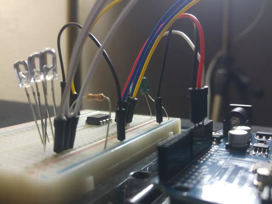
Building the Circuit
We are ready to jump into building the programming circuit.
- Unplug your Arduino
- Place the ATtiny Chip onto the breadboard
- Connect the ground from the Arduino to the Ground Rail
- Connect the 5V from the Arduino to pin 8 of the ATTINY
- Connect pin 4 of the chip to ground
- Place the capacitor between ground and another terminal strip (The anode of the capacitor must be connected to ground)
- Connect the cathode of the capacitor to the Reset pin of the Arduino
- Connect a lead from the header pin 10 of the Arduino to pin 1 of the chip
- Connect Arduino Pin 11 to Pin 5 of the chip
- Connect Arduino Pin 12 to Pin 6 of the chip and
- Connect Arduino Pin 13 to Pin 7 of the ATtiny85
Add LEDs
The programmer will now work, but I'm going to add some LED's because LED's are fun to have.
- Connect the 330k resistor to ground and a terminal strip.
- Connect Arduino pins 7, 8 and 9 to separate terminal strips.
- Place LED's between each of the terminal strips (connected to 7, 8 and 9) and to the terminal strip with the 330k Resistor.
Back to Arduino IDE
Head back over to the Arduino IDE. First we need to burn the Bootloader to the chip.
Once that is done, you can upload Arduino Sketches to the ATtiny chip, as if it were an Arduino.
Just remember the limitations to the ATtiny chip and any program within its limitations will work.