Learn how to build a weight measuring system with an Arduino, HX711, and a load cell.
In this tutorial, I will explain how to build a weighing scale with an Arduino, an HX711, and a load cell.
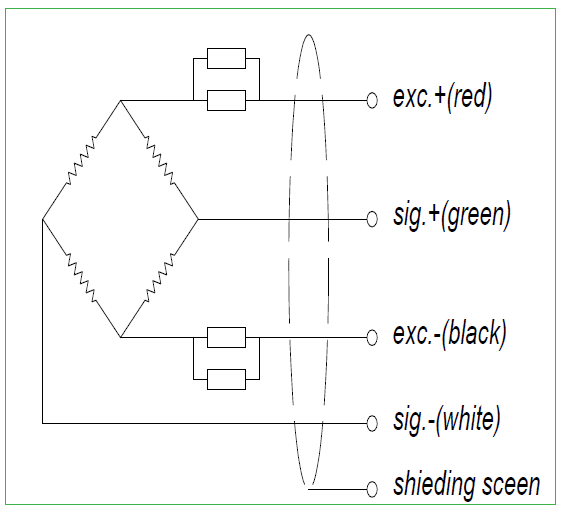
Electronic weighing machines use load cells to calculate the load or the actual pressure produced by the load. There are many types of load cells and each follows the method of strain gauge, which converts the pressure (force) into an electrical signal in real time. These load cells consist of four strain gauges hooked up in a Wheatstone bridge formation.
Wheatstone Bridge Formation of the Load Cell
Whenever we apply the load, the resistance of the strain gauge in the load cell will change. Hence, the output voltage from the load cell changes allowing us to measure the load value.
The Wheatstone bridge formation of a load cell.
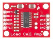
HX711
The HX711 is a precision 24-bit analog to digital converter (ADC) designed for weigh scales and industrial control applications to interface directly with a bridge sensor.
It is specially designed for high precision electronic scale design, with two analog input channels, and a programmable gain amplifier. The input circuit can be configured to provide a bridge type configuration. It is very precise, affordable, and works well for sampling a front-end module.
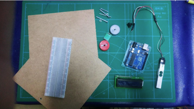
Required Hardware
- Load cell
- HX711 module
- Arduino
- Some jumper wires
- Character LCD 16X2
- Cardboard, bottle caps, and some bolts
The project's required materials.
A load cell’s range can vary greatly. In the project, we use a load cell that can weigh up to 20kg. We will also be using a character LCD to display the load cell’s reading.
Wiring
Wire everything as listed in the table below.
LCD Pin | Arduino |
|---|
1 (VSS) | GND Arduino Pin* |
2 (VDD) | + 5V Arduino Pin |
3 (Contrast) | Resistor or potentiometer to ground |
4 RS | Arduino pin 12 |
5 R/W | Arduino pin 11 |
6 Enable | Arduino pin 10 |
7 No connection | |
8 No connection | |
9 No connection | |
10 No connection | |
11 (Data 4) | Arduino pin 5 |
12 (Data 5) | Arduino pin 4 |
13 (Data 6) | Arduino pin 3 |
14 (Data 7) | Arduino pin 2 |
15 Backlight + | Resistor to Arduino pin 13** |
16 Backlight GND | GND Arduino pin* |
Connect the load cell wires to the HX711 module based on their color. Then connect DAT (data) pin to Arduino Analog pin A3 and connect CLK (clock) pin to Arduino analog pin A2. Connect Vcc and GND supply from Arduino power source pins. Also, connect a simple push button for calibration.
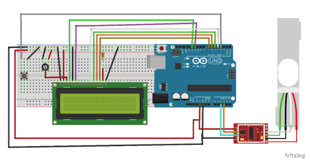
Here is the Fritzing diagram:
Fritzing diagram of the load cell to the HX711 module.
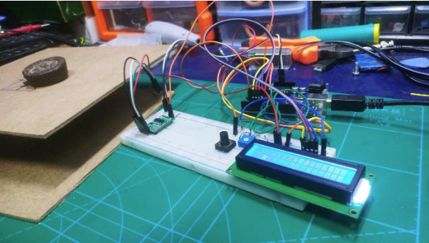
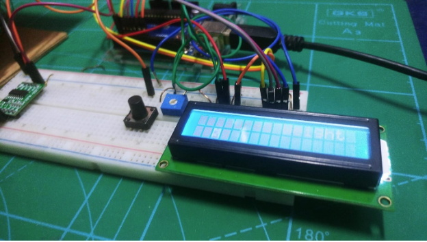
When everything is connected, it should look like this:
The actual circuit connection.
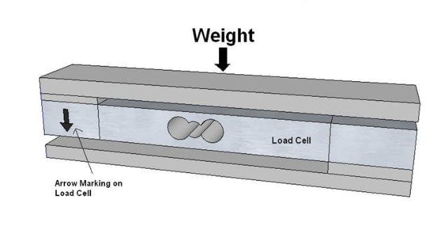
Setting Up the Load Cell
Look for the arrow when you're setting up the load cell.
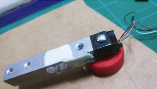
Check the arrow on the load cell. It tells us the direction that we need to apply force. You can assemble the load cell as shown in the figure above using metal strips. Just attach the metal strip on the load cell using bolts. Or you can simply attach bottle caps with bolts by making a hole in the bottle caps as I did in the image below.
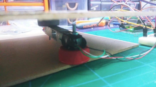
Attached bottle cap with bolts to the load cell.
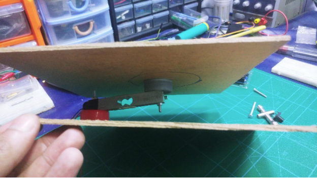
The load cell build between the pieces of cardboard.
Another view of the load cell build.
Project Source Code
#include <LiquidCrystal.h>
const int rs = 12, en = 11, d4 = 4, d5 = 5, d6 = 6, d7 = 7;
LiquidCrystal lcd(rs, en, d4, d5, d6, d7);
#define DT A2
#define SCK A3
#define sw 3
long sample=0;
float val=0;
long count=0;
unsigned long readCount(void)
{
unsigned long Count;
unsigned char i;
pinMode(DT, OUTPUT);
digitalWrite(DT,HIGH);
digitalWrite(SCK,LOW);
Count=0;
pinMode(DT, INPUT);
while(digitalRead(DT));
for (i=0;i<24;i++)
{
digitalWrite(SCK,HIGH);
Count=Count<<1;
digitalWrite(SCK,LOW);
if(digitalRead(DT))
Count++;
}
digitalWrite(SCK,HIGH);
Count=Count^0x800000;
digitalWrite(SCK,LOW);
return(Count);
}
void setup()
{
pinMode(SCK, OUTPUT);
pinMode(sw, INPUT_PULLUP);
lcd.begin(16, 2);
lcd.print(" Weight ");
lcd.setCursor(0,1);
lcd.print(" Measurement ");
delay(1000);
lcd.clear();
calibrate();
}
void loop()
{
count= readCount();
int w=(((count-sample)/val)-2*((count-sample)/val));
lcd.setCursor(0,0);
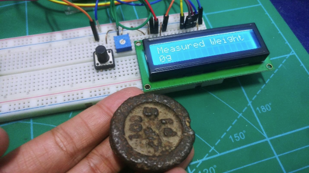
lcd.print("Measured Weight");
lcd.setCursor(0,1);
lcd.print(w);
lcd.print("g ");
if(digitalRead(sw)==0)
{
val=0;
sample=0;
w=0;
count=0;
calibrate();
}
}
void calibrate()
{
lcd.clear();
lcd.print("Calibrating...");
lcd.setCursor(0,1);
lcd.print("Please Wait...");
for(int i=0;i<100;i++)
{
count=readCount();
sample+=count;
}
sample/=100;
lcd.clear();
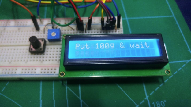
lcd.print("Put 100g & wait");
count=0;
while(count<1000)
{
count=readCount();
count=sample-count;
}
lcd.clear();
lcd.print("Please Wait....");
delay(2000);
for(int i=0;i<100;i++)
{
count=readCount();
val+=sample-count;
}
val=val/100.0;
val=val/100.0; // put here your calibrating weight
lcd.clear();
}
Testing the System
After uploading the code, put the 100g weight and wait for calibration. After calibration, weight measurement should proceed normally.
Put 100g on the build and wait for calibration.
After calibration, your LED screen will show that it's ready to weigh objects!