Learn more about the characteristics and rules of voltage and see how these rules apply to divider circuit design.
While a full in-depth knowledge of electronics is not necessarily required when designing and building projects, it definitely helps to know a few basics. In this article, we will learn about the behavior of voltage and how resistors can be used to create divider circuits.
Before you delve into voltages and dividers, refresh your memory of Ohm's Law and how it relates to circuit design!
What is Voltage?
Voltage is one of the fundamental units in electronics and can be thought of as a pushing force. Voltage is often categorized into two terms: electromotive force (EMF) and potential difference (PD).
When something provides a voltage (such as a battery or power supply), it is said to have an EMF because it provides the force needed to pull electrons along a circuit. When a component “consumes” a voltage in a circuit, the amount of voltage drop across it is referred to as potential difference. A few rules surround voltage which can help with circuit design. These rules include:
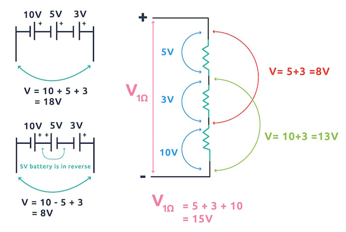
- Voltages in series add up
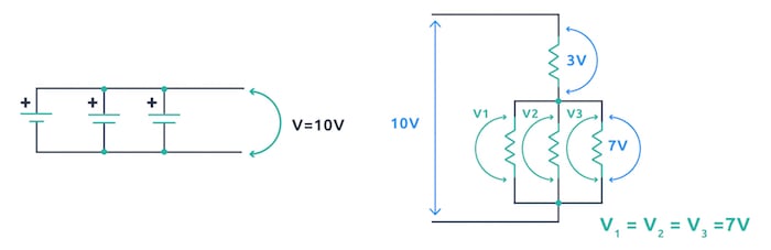
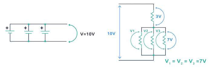
- Voltages in parallel are always the same
- The size of the PD across a component is directly proportional to its resistance
- Polarity is everything—make sure to keep an eye on it!
- The sum of the EMF’s around a circuit equals the sum of the PDs
"Voltages in series always add up" applies to both EMF and PD. If batteries are placed in series then their voltages add up and if there are components in series then you can take voltages across multiple components and their combined PD is what the output will be. While potential differences are easy to determine, make sure that you keep an eye on the polarity of power sources as batteries in reverse subtract from the combined voltage!
An example of how voltages in a series add up.
Voltages in parallel are always the same in parallel which is one of the reasons why putting batteries in parallel whose voltages are different is not a good idea. When two batteries which have difference voltages are connected in parallel the battery with the larger voltage will attempt to put charge into the smaller battery which can damage the smaller battery.
An example of voltages in parallel.
Simple Divider Circuits
We have seen that voltages in series add up and voltages in parallel are the same but how do voltages split up across components in a series circuit? What determines the voltage across each component? This splitting up of voltage (called potential difference), is determined by the ratio of the resistance of a component compared to the resistance of the series circuit that it’s in. This is directly related to the voltage rule:
“The size of the PD across a component is directly proportional to its resistance”
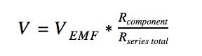
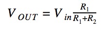
Essentially, this means that the larger the resistance a component has (when compared to the series circuit it lies in), the larger the potential difference across it will be. In fact, the voltage across a component is equal to
When considering the classic divider circuit the formula is often written as
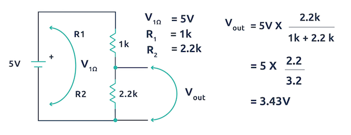
Below is an example of the classic potential divider circuit being used to provide approximately 3.3V from a 5V source.
(Hint: This circuit can be used to connect a 5V output device to a 3.3V input on a microcontroller such as the Particle Photon.)
An example of the classic potential divider circuit.
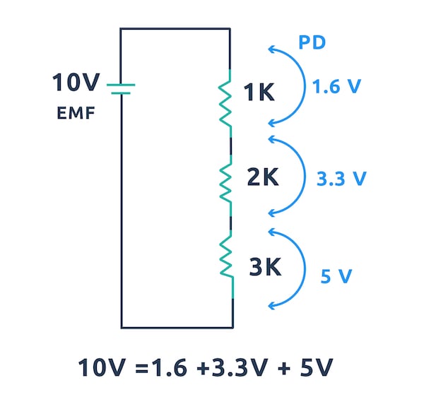
When a voltage (EMF) is applied to a circuit, the sum of all of the potential differences across the series components will be equal to the EMF. This is hard to understand as a written sentence but when seen as an example it makes sense. Voltages provided by a battery will divide up across components that are in series and the sum of all those divided voltages will be equal to the battery's voltage!
The sum of the potential differences across the series will be equal to the EMF.