Learn how to incorporate gesture control into your project through this Arduino and LED strip project!
In this article, we will explore the APDS-9960 gesture sensor and how to use it to control a Neopixel LED strip with WS2812B.
We can use simple gestures for controlling the LED strip. Moving your hand from left to right will change the direction of the running LEDs and moving your hand up and down will change its color.
The APDS-9960 RGB and Gesture Sensor
The APDS-9960 RGB and gesture sensor is a really tiny breakout board that comes with ambient light, color measurement, proximity detection, and touchless gesture ability.
The APDS-9960 RGB and gesture sensor.
This sensor is multifunctional, it can also be used as a proximity sensor. It is mostly used in smartphones to reduce the screen brightness when in a dark environment, or for disabling the touchscreen when answering a phone call. This is exactly the same sensor that was used in the Samsung Galaxy S5 and is probably one of the cheapest and best gesture sensor modules in the market.
Built with UV blocking filters and four separate sensor diodes for four different directions, this sensor module is compatible with I2C protocol and is very easy to integrate with Arduino.
Sensor Pinout
- VL (this is optional power for IR LED)
- GND (Ground)
- VCC (For powering up the module)
- SDA (I2C data)
- SCL (I2C clock)
Sensor Specs
- Operational voltage: 3.3V
- Size: 20mm X 15.3mm
- I2C interface (0X39)
- Ambient light
- Proximity
- Gesture direction
WS2812B LED Strip
The WS2812B LED strip comes with 5050 RGB LED lights and have the very compact WS2812B LED driver IC integrated into them.
The WS2812B is an addressable LED strip that comes in several models, different sizes, and LED density. In this project, I am using a 1-meter strip with 30 WS2812B-based LED lights. The LEDs are water and dustproof as they are enclosed in a waterproof silicone casing.
The LED strip is encased in a waterproof silicone casing.
The LEDs are connected in series, and since the driver is integrated into the LED, each one is addressable. Having addressable LEDs allows us to control the brightness and color of each LED individually, producing complex effects easily. Also, this LED strip is really flexible and can be cut to any length.
A close up of the driver IC on the LED strip.
Now that we have a solid understanding of our key pieces of hardware, let’s dive into the project!
Required Software
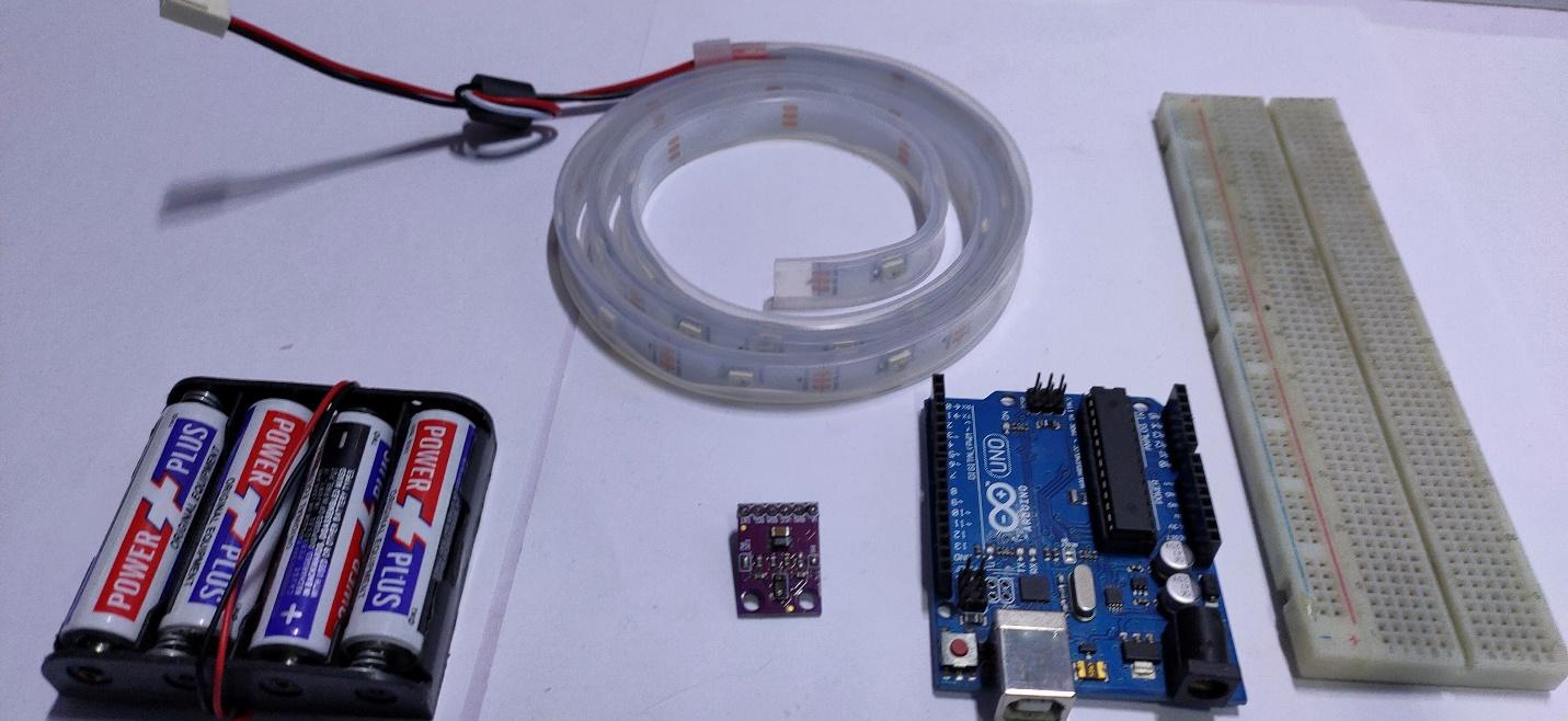
Required Hardware
- Arduino UNO
- APDS-9960 sensor
- WS2812B LED strip
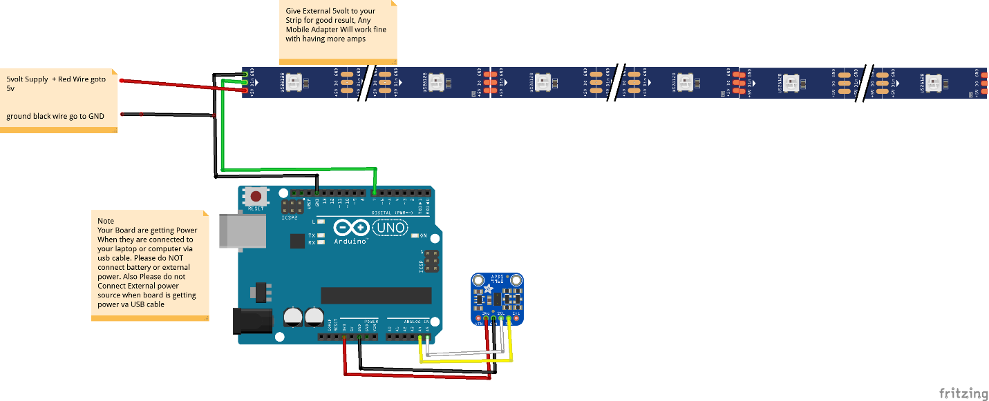
Wiring the Hardware
**Note: You must use 3.3V in order to power this module; if you try to use more than 3.3V supply, you risk damaging the APDS-9960.
Connecting the APDS-9960 I2C to Arduino
SCL pin of the APDS9960 should be connected with SCL pin on your Arduino. This pin differs depending on your board model. Here are some common pin numbers:
- Arduino Uno: A5
- ATmega385-based Arduinos: A5
- Leonardo: 3
- Arduino Mega: 21
The SDA pin should be connected with I2C data SDA pin on your Arduino. In Arduino Uno or Atmega385 based Arduino, this is the A4 pin, in Leonardo it’s 2 and in Arduino Mega it’s 20.
VCC should be connected with 3.3V and GND to GND.
Connecting the WS2812B With Arduino
The ground pin of the LED strip should be connected with Arduino GND and the data pin of WS2812B should be connected with Arduino Pin 7.
For best results, connect the 5+ pin of the LED strip to an external power supply. You can use a phone charger for this. If you have a 30 LED strip, this draws 1.5A in total, and each LED draws 50mA.
I am using the Arduino’s 5V pin to power the strip because I don’t care about the brightness. However, if you want to control more LEDs you must use an external power source.
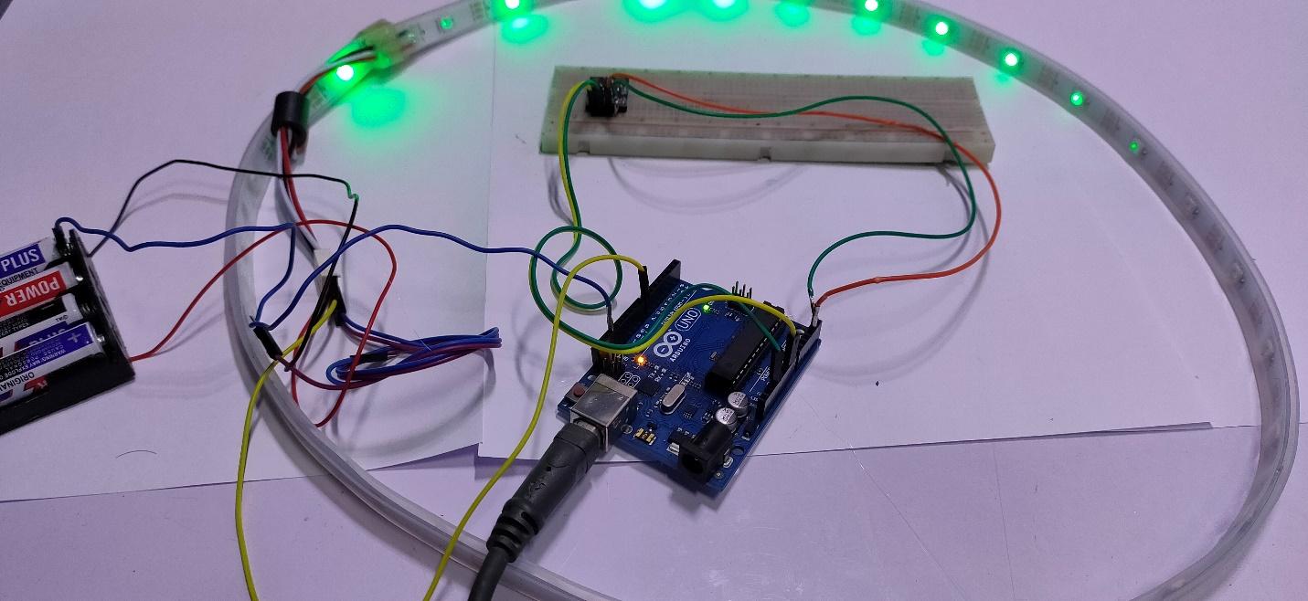
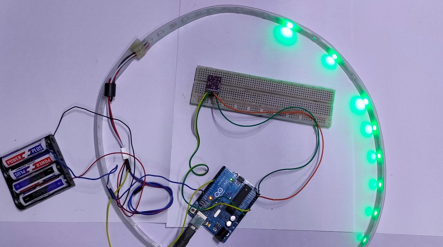
The project hardware connected and powered on.
Download Libraries and Upload Source Code To Arduino IDE
Next, we need to upload the source code (click the link to access the code) and download the libraries for Arduino IDE.
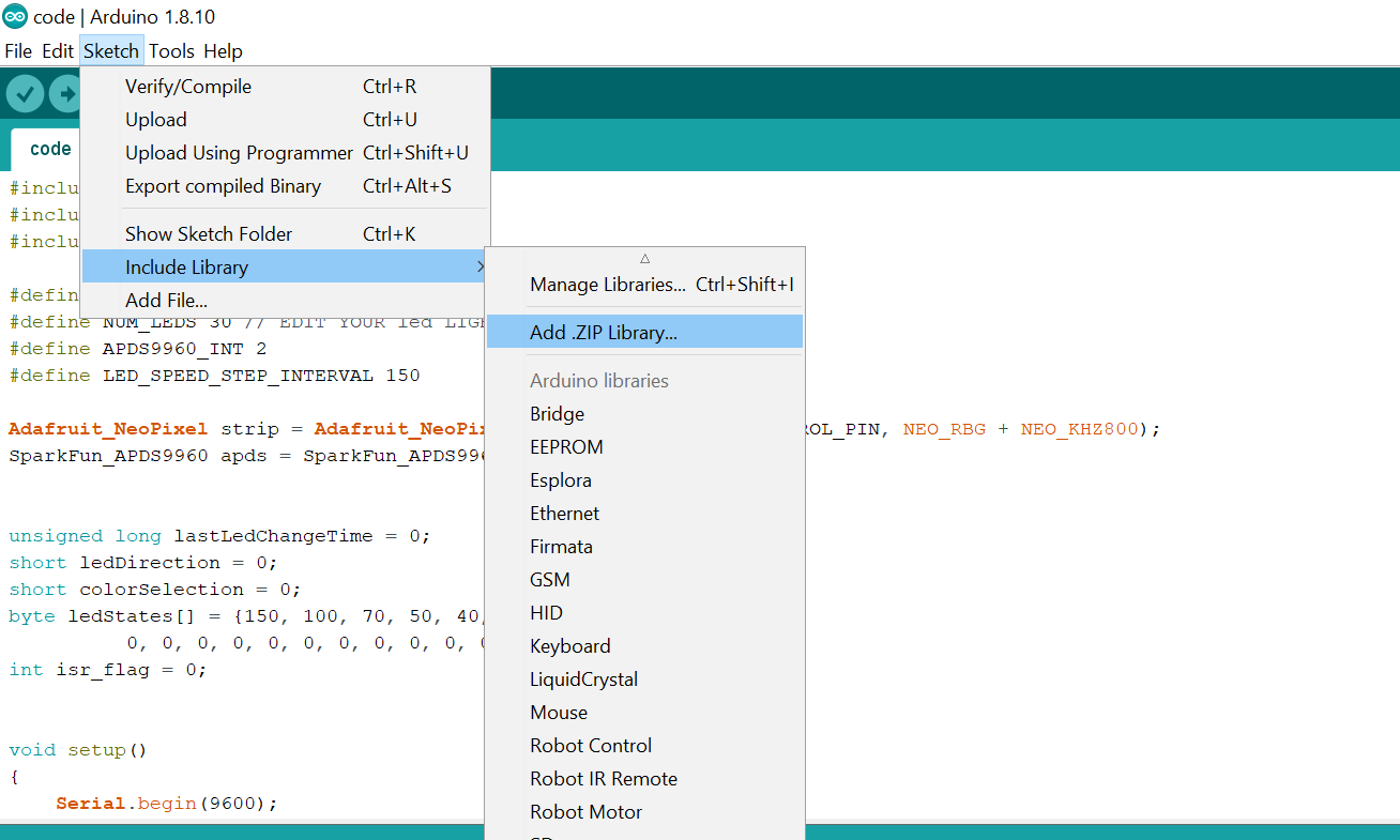
To upload the library to Arduino IDE, follow the steps below.
Go to Sketch —> Include Library —> Add.ZIP Library. Repeat these steps for all libraries.
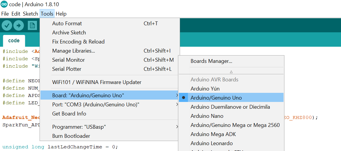
After adding the libraries, connect you Arduino board with your computer. Then go to Tools —> Board —> Select Arduino UNO board.
Go to Tools —> Port —> COM PORT. In my case, it’s COM3.
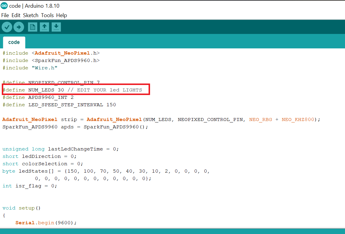
Before uploading the code make sure to change the number of LEDs inside the Arduino Sketch according to your requirements. This example uses a 30 LED light strip.
Copy and paste the code to your Arduino, then select Upload.
After uploading the code, you can test your project. In order to test, move your hand left to right above the sensor and observe the LED strip animation. You can see my project test in the video below.