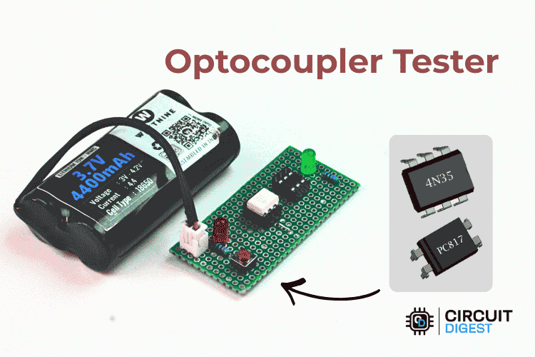
Quickly check 4-pin and 6-pin optocouplers with a pocket-sized tester and two LEDs.
Optocouplers are widely used in power supplies, motor drives, and microcontroller projects to provide electrical isolation between circuits. When an optocoupler fails, it often shows no visible signs of damage, making troubleshooting frustrating and time-consuming.
This simple tester solves that problem by checking both the input LED and output transistor of an optocoupler in just a few seconds. With only a handful of components, you can build a compact tool that instantly tells you whether a device is good or faulty.
What Is an Optocoupler?
An optocoupler (also called an optoisolator) transfers a signal using light instead of a direct electrical connection.
Inside the package are two components:
- An infrared LED on the input side.
- A phototransistor (or similar photosensitive device) on the output side.
When current flows through the internal LED, it emits light that activates the output transistor. This allows two circuits to communicate while remaining electrically isolated.
Common optocouplers include the PC817, MOC3021, and 4N35.
Why Build an Optocoupler Tester?
Testing optocouplers with a multimeter can confirm whether the internal LED is intact, but it does not always verify that the output side is working properly.
This dedicated tester offers several advantages:
- Tests both input and output sections simultaneously
- Provides an immediate visual PASS/FAIL result
- Works with both 4-pin and 6-pin devices
- Battery-powered and portable
- Easy to build using inexpensive parts
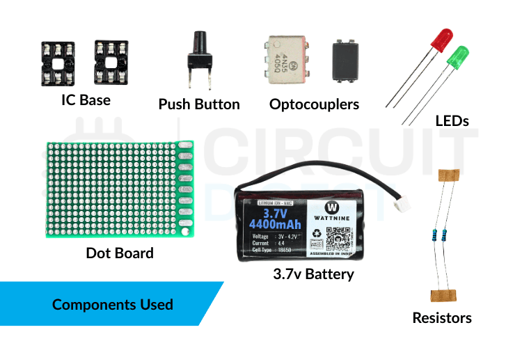
Components Required
You only need a few common components:
- 1 × Red LED
- 1 × Green LED
- 2 × 470 Ω resistors
- 1 × Push button switch
- 1 × 3.7 V Li-ion battery or 3–5 V supply
- 1 × 4-pin IC socket
- 1 × 6-pin IC socket
- 1 × Small perfboard or stripboard
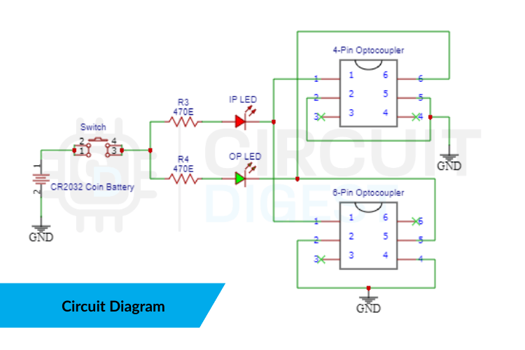
Circuit Overview
The tester consists of two indicator stages:
Input Test Stage
When the push button is pressed, current flows through:
- The optocoupler’s internal LED
- A current-limiting resistor
- The red LED indicator
If the red LED lights, the internal LED is conducting.
Output Test Stage
If the optocoupler is functioning correctly, the internal light activates the output transistor, which completes the circuit for the green LED.
If the green LED lights, the output stage is working.
How the Tester Works
Press the push button after inserting the optocoupler into the socket.
Both LEDs ON
Result: Optocoupler is good.
Red LED ON, Green LED OFF
- Input LED works
- Output transistor does not respond
Result: Optocoupler is faulty.
Both LEDs OFF
- No current through the internal LED
- Incorrect insertion or damaged input LED
Result: Check orientation or replace the device.
Green LED ON, Red LED OFF
This condition is unusual and usually indicates a wiring error or a shorted output transistor.
Building the Circuit
- Mount the 4-pin and 6-pin IC sockets on a small perfboard.
- Add the red and green LEDs.
- Connect the resistors in series with each LED.
- Wire the push button to apply power only during testing.
- Connect the battery holder or DC input.
- Verify all wiring before inserting any optocoupler.
Using IC sockets prevents heat damage and lets you test multiple devices repeatedly.
Testing an Optocoupler
- Identify the device pinout.
- Insert the optocoupler into the appropriate socket.
- Press and hold the push button.
- Observe the LEDs.
- Remove the device and test the next one.
Each test takes only a few seconds.
Compatible Devices
This tester can be used with many common optocouplers, including:
Always verify the pin configuration before testing.
Advantages of This Tester
- Very low cost
- Fast and easy to use
- Portable and battery-powered
- Suitable for beginners and repair technicians
- No multimeter required
Limitations
This circuit performs a functional go/no-go test. It does not measure:
- Current Transfer Ratio (CTR)
- Switching speed
- Leakage current
- Isolation voltage
For detailed characterization, laboratory instruments are required.
Practical Applications
A dedicated optocoupler tester is useful for:
- SMPS repair
- Inverter servicing
- Industrial control maintenance
- Sorting salvaged components
- Educational demonstrations
Troubleshooting Tips
Red LED Does Not Light
- Check optocoupler orientation
- Verify resistor values
- Confirm battery voltage
Green LED Does Not Light
- Output transistor may be damaged
- Wrong pin mapping
- Poor socket contact
LEDs Glow Dimly
- Low battery
- Incorrect resistor values
- Weak optocoupler
Multimeter vs Dedicated Tester
A digital multimeter can confirm that the internal LED is not open, but it often cannot prove that the output transistor switches correctly.
This tester checks the actual optical coupling action, making it more reliable for real-world troubleshooting.
Final Thoughts
If you regularly repair electronics or work with isolation circuits, this optocoupler tester is a practical addition to your workbench. It is inexpensive, easy to build, and provides instant results with no guesswork.
Whether you are testing a single PC817 or sorting a batch of salvaged parts, this compact tool can save valuable time and help you avoid installing faulty components. Explore Circuit Digest’s collection of 200+ electronic circuit projects and tutorials to find step-by-step guides, circuit diagrams, and tested DIY electronics projects idea for beginners and professionals alike.