Learn the different methods of extending the number of IO lines on an Arduino using decoders and shift registers.
More elaborate projects often require you to use a large number of a microcontroller’s input and output lines. You can use a few methods to make it look like the microcontroller has more inputs and outputs than it really does. This article discusses a few common methods.
Extend Outputs with Decoders
Decoders allow you to output 2n signals using n output lines. You can either use AND logic gates (which I wouldn’t recommend) or you can get a readily available decoder IC that does the work for you.
In the circuit above, I used a 4028 BCD (binary coded decimal) decoder. This allowed me to use four GPIO lines of an Arduino to control ten individual transistors and thereby switch ten different symbols on and off in a nixie tube.
The decoder method can be used whenever you want to activate one signal at a time. It isn’t possible to enable two or more of the ten outputs simultaneously. However, because the input gets supplied via parallel data lines, this method usually allows for fast switching.
Extend Outputs With a Shift Register
This method also allows you to extend outputs. However, unlike decoders, the data gets clocked into a shift register one bit at a time and is therefore usually a slower method. Using a serial to parallel shift register will, however, allow you to output multiple bits at the same time. Additionally, it’s also possible to daisy-chain the shift-registers, which makes it possible to drastically extend the number of available outputs.
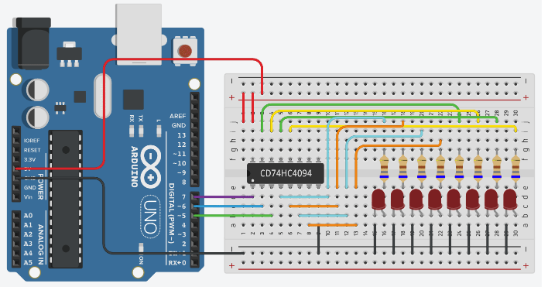
The following example illustrates how to use three control lines to create eight additional output lines for an Arduino:
While it might look complicated, it really isn’t. The yellow, green, cyan, and orange lines are the eight outputs. The LEDs serve as a display. The purple, blue, and green connections to the Arduino are necessary for controlling the shift register and sending the serial data. Everything else is done by the software on the Arduino.
Extending Input Lines With a Shift Register
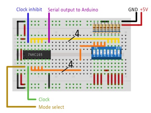
So far, the methods discussed for extending IO lines only allowed us to output more bits while using fewer output lines. However, it’s also possible to read multiple inputs while only occupying one input pin of a microcontroller. This method uses shift registers, just like the example above. However, while the circuit for extending outputs used a serial to parallel register, extending inputs requires a parallel to serial shift register.
I discussed shift registers in general and this particular circuit in another article so I won’t explain it in any more detail here but do recommend you read the shift registers article if you’re new to the concept.
If you need even more inputs or outputs, you can cascade shift registers. However, keep in mind that each stage you add reduces the overall speed of your system.
Extending Input Lines With an Encoder
Just like with shift registers, there’s also a counterpart to the decoder used in the first example: the encoder. Encoders allow you to have 2ˆn input lines and will select one of the n outputs that can then be read by a microcontroller.
This enables you to determine which of the input lines got activated which, for example, can be used to read the state of a rotary switch.
Summary
There are multiple ways of making a microcontroller appear to have more IO lines. These techniques can be used if your external circuitry requires more GPIO lines than your microcontroller can offer or if you simply don’t want to use all of them to keep the number of external connections small.
However, the overall speed of your circuit might decrease and you’ll need additional ICs. It’s also important to determine whether you want a selector, where a single output is active, or where any number of outputs can be active simultaneously.