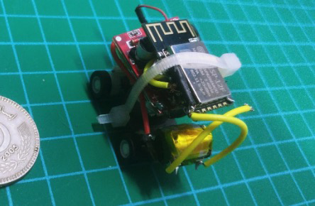
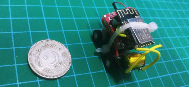
Learn how to build your coin-sized robot car controlled wirelessly using an ESP8266, a motor driver, and some batteries.
In this article, I will explain how to build a coin-sized robot car that can be controlled over the Internet using an ESP8266, a motor driver, and some batteries.
The ESP8266 is a low-cost Wifi microchip with full TCP/IP stack and microcontroller capability produced by Shanghai-based Chinese manufacturer Espressif System.
The motor driver we’re using is a tiny motor driver called the MX1508, which is a smaller alternative to the L298N motor driver module. To control the robot, we’re using the Blynk mobile app platform.
What is Blynk?
Blynk is a platform based on iOS and Android that lets you talk to Arduino and Raspberry Pi over the Internet. It's a digital dashboard where you can build a graphic interface for your mobile apps project by simply dragging and dropping widgets.
Note that while Blynk is free to get started, you may need to pay for extra “energy” to build more complex apps. The app to run this article, however, is possible without an extra purchase.
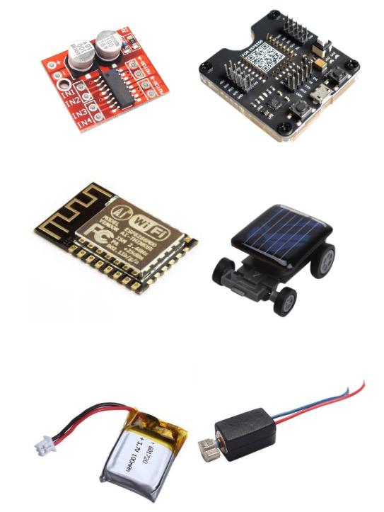
Required Hardware
- ESP12E
- ESP8266
- 150mah battery pack
- Some wires
- A small car with a vibratory motor or a small solar car
- MX1508 motor driver
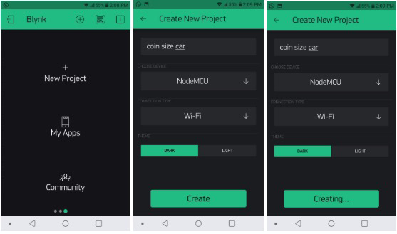
Configuring the Blynk App
Start by signing up with Blynk. Then tap on New Project, name your project, and select the device as “nodeMCU” and select “Wi-Fi”. Tap on “Create”.
After tapping Create, Blynk will send you an email with your project authentication token code to use. After creating your project, add a couple of buttons by Tapping on “+”.
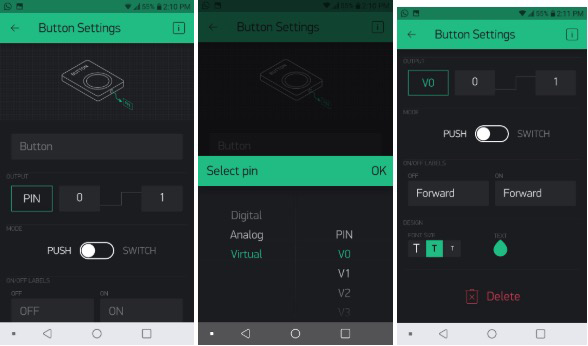
Once you add the buttons, configure them as shown in the screenshots below.
Select the pin Virtual>V0 for the first button and name your button “Forward”.
Name the second button “Backward” and select the pin Virtual>V4. You can repeat these steps if you want to add left and right controls but for now, we are testing this with forward and backward.
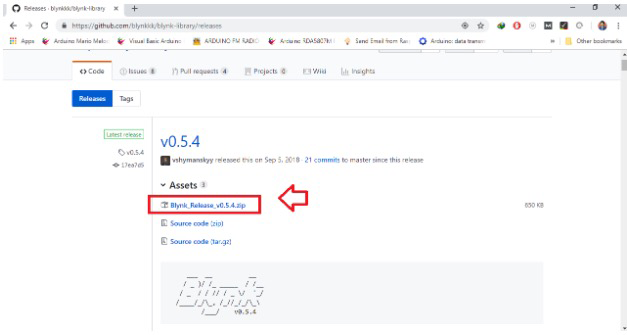
Upload source code
For beginners, follow the steps in Programming ESP/NODEMCU with Arduino IDE to set up Arduino IDE for this project. I recommend you use the ESP8266 development board for uploading the source code if you just have the standalone chipset.
Note: Before uploading the program, change the SSID, password, and auth code to fit your program in the source code. After changing in the source code, hit the upload button.
#define BLYNK_PRINT Serial

#include <ESP8266WiFi.h>
#include <BlynkSimpleEsp8266.h>

// You should get Auth Token in the Blynk App.
// Go to the Project Settings (nut icon).
char auth[] = "--your authenticate code--";

// Your WiFi credentials.
// Set password to "" for open networks.
char ssid[] = "your wifi";
char pass[] = "your wifi password";

// These are used to set the direction of the bridge driver.
#define ENB D3      //ENB
#define MOTORB_1 D4 //IN3
#define MOTORB_2 D5 //IN4


// SETUP
void setup()
{

  pinMode(ENB, OUTPUT);
  pinMode(MOTORB_1, OUTPUT);
  pinMode(MOTORB_2, OUTPUT);

 // digitalWrite(ENA,LOW);
  digitalWrite(ENB,LOW);

  // Start serial communication
  Serial.begin(9600);

  // Connect Blynk
  Blynk.begin(auth, ssid, pass);
}


// FORWARD
BLYNK_WRITE(V0) {
  int button = param.asInt(); // read button
  if (button == 1) {
    Serial.println("Moving forward");

    digitalWrite(ENB,HIGH);

    digitalWrite(MOTORB_1,LOW);
    digitalWrite(MOTORB_2,HIGH);
  }
  else {
    Serial.println("Stop");

    digitalWrite(ENB,LOW);

    digitalWrite(MOTORB_1,LOW);
    digitalWrite(MOTORB_2,LOW);
  }
}
// BACKWARD
BLYNK_WRITE(V3) {
  int button = param.asInt(); // read button
  if (button == 1) {
    Serial.println("Moving backward");

    digitalWrite(ENB,HIGH);

    digitalWrite(MOTORB_1,HIGH);
    digitalWrite(MOTORB_2,LOW);
  }
  else {
    Serial.println("Stop");

    digitalWrite(ENB,LOW);

    digitalWrite(MOTORB_1,LOW);
    digitalWrite(MOTORB_2,LOW);
  }
}

// MAIN CODE
void loop()
{
  Blynk.run();
}
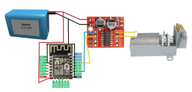
Wiring the ESP8266 Bot
After uploading the source code, wire up everything as shown in the diagram below. Remove the solar plate from the car, assemble the eSP8266 and MX1508 motor driver module with a battery.
We will only be using a single motor, so the bot will only be able to move forward and backward. You can add one more motor later to make a differential drive.
After wiring, open your Blynk app. Choose the Blynk project and then tap “Play”. The project will start. Since Blynk is an IoT platform, this tiny car can be controlled over the internet using the mobile app.