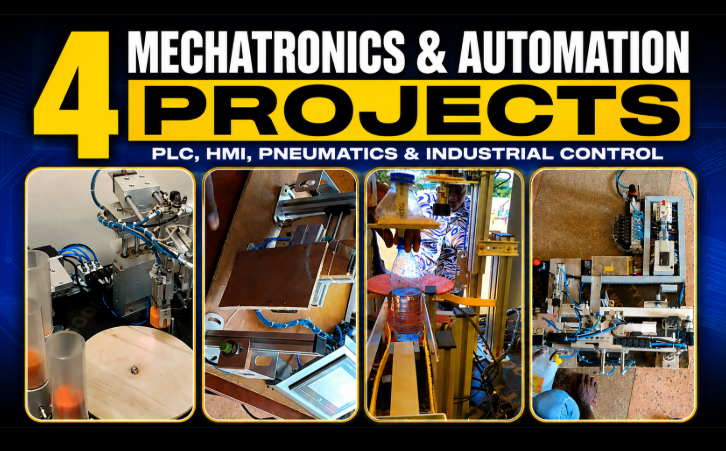
1. Smart Sorting System
An operator picks a storage compartment, one of three, from an HMI panel, and a robotic mechanism retrieves the item and delivers it to a pickup point for the next stage of handling. It's a request-then-fulfill system: it sits idle until a selection is made, runs one complete retrieval cycle, and returns to ready.
The real engineering challenge here isn't the motion itself; it's confirming the motion actually worked, making sure the robot actually picked something up before it reports success, rather than placing an empty gripper and moving on. That's the difference between a system that looks automated and one that's actually reliable.
Common components for a system like this:
- PLC and HMI panel (for compartment selection and status)
- Robotic pick-and-place mechanism — pneumatic cylinders or motor-driven axes, depending on the build
- Gripper or other end effector to hold the item during transport
- Position sensors or limit switches to confirm the robot has reached each compartment
- An item-presence sensor to confirm a successful pick and a successful drop-off
- Conveyor motor for the pickup/transfer stage
2. Pneumatic Entrance and Occupancy Control
A keypad grants entry, a pneumatically actuated door opens and closes, and separate sensors at the entrance and exit track how many people are inside — incrementing the count on entry, decrementing it on exit. An HMI gives an operator manual override.
The interesting design problem is keeping three separate functions distinct: detecting someone (a raw sensor event), counting them (deciding whether that event should change the occupancy number), and controlling access (deciding whether the door should open at all). Blur those together and the logic gets fragile fast — a person who lingers near a sensor can get double-counted, or a keypad entry can bypass an occupancy limit that should have blocked it.
Common components for a system like this:
- PLC and HMI panel (for override, occupancy display, and fault reset)
- Keypad for entry codes
- Pneumatic cylinder for the door, driven through a solenoid-actuated directional control valve
- Compressed air supply for the pneumatic circuit
- Separate entrance and exit sensors (commonly photoelectric) to establish direction of travel
- Door position sensing (limit switches or similar) to confirm open/closed states
3. Bottle Filling and Capping with Turntable
This is the one project from the video with a full public build log, so the details below are confirmed, not illustrative. The line runs on a PLC with an INOVANCE IT6000 HMI (designed in INOTOUCH Editor, programmed via GX Works), a 24V mini fluid pump for filling, a double-acting pneumatic cylinder through a directional control valve, and a high-torque conveyor feeding a rotary turntable.
A bottle placed on the conveyor is detected by an optical sensor, carried to the fill station, held for a timed fill, then moved to the turntable — which rotates it through capping and inspection over several turns before ejecting it. If the bottle fails inspection (a missing cap, for example), the turntable holds position instead of ejecting it. The HMI itself has two screens: a main screen for start/stop and fill/cap timing, and a parameter screen with Full/Half/Low fill presets so operators can switch products without reprogramming anything.
Confirmed components used in this build:
- PLC, programmed and loaded via GX Works
- INOVANCE IT6000 HMI, screens designed in INOTOUCH Editor
- Non-contact control panel using capacitive sensors
- 24V mini fluid pump for filling
- Double-acting pneumatic cylinder with a directional control valve (DCV)
- High-torque conveyor belt
- Rotary turntable for capping and inspection
- Optical sensor at the conveyor start point
- E-stop and physical start/stop pushbuttons alongside the HMI Start command
Full write-up and CAD/PLC files: DIY Industrial Production Line Filling and Capping System on Maker Pro.
4. Multi-Stage Bottle Filling and Capping
The most physically distributed of the four: an empty bottle is detected, pushed into position, filled, then carried by a second conveyor to a separate capping station. There, pneumatic cylinders clamp the bottle in place, a gripper picks up a cap and sets it, and a motor tightens it down.
Splitting filling and capping into two physically separate stations (rather than one line, as in Project 3) means the two operations can run more independently — the next bottle can start filling while the previous one is still being capped. The clamping step is the one hard rule the whole station depends on: capping should never be allowed to start until the bottle is confirmed clamped, or the tightening motor just spins the bottle instead of the cap.
Common components for a system like this:
- PLC and HMI (for station status, production counts, and manual control)
- Bottle-detection sensor at the infeed
- Pneumatic pusher cylinder for positioning the bottle at the fill station
- Fill valve or pump for the filling operation
- A second conveyor to transfer bottles from filling to capping
- Pneumatic holding/clamping cylinders at the capping station
- A gripper for picking and placing the cap
- A motor for tightening the cap once placed
The Common Thread
All four systems boil down to the same loop, just applied to different problems: sensor → controller → actuator → confirm it worked → repeat. Where they differ is in how much they lean on synchronization (Project 3's fill/index/cap timing), interlocking (Project 4's clamp-before-capping rule), or directional logic (Project 2's entrance vs. exit counting). Understanding that shared structure is really what makes it possible to design a fifth project — or a real production line — using the same building blocks.
If you're building something similar and want help with the PLC sequence, HMI layout, or write-up, reach out at [email protected].