Learn how you can use a simple, custom test PCB to help program and test the ATtiny series of AVR microcontrollers.
We’ve taken a look at the differences between Arduinos and the ATtiny series AVR microcontrollers in terms of their specifications. However, another major difference between the two lies in how the microcontrollers are programmed.
Arduino boards can be programmed by simply plugging the boards into a computer via USB. The boards incorporate a number of peripheral components, in addition to a bootloader, that allows them to be programmed without any special connections or software.
However, this is not the case with the ATtiny series microcontrollers. There are several different ways to program the ATtiny series microcontrollers depending upon the scale of your project.
Ways to Program ATtiny Microcontrollers
One way to program ATtinys has already been covered on Maker Pro is using an Arduino Uno as an ISP programmer. Using an Arduino as an AVR programmer is a good option for prototyping single units, but it is impractical for businesses producing a product. This is especially the case for designs using SMD microcontrollers as these cannot be plugged into an Arduino or breadboard.
In this article, we will be taking a look at three different methods of programming your ATtiny microcontrollers that allow for programming SMD packages, and can be used for scaling up production from small prototype runs of under 100 units, up to runs of tens or hundreds of thousands of units:
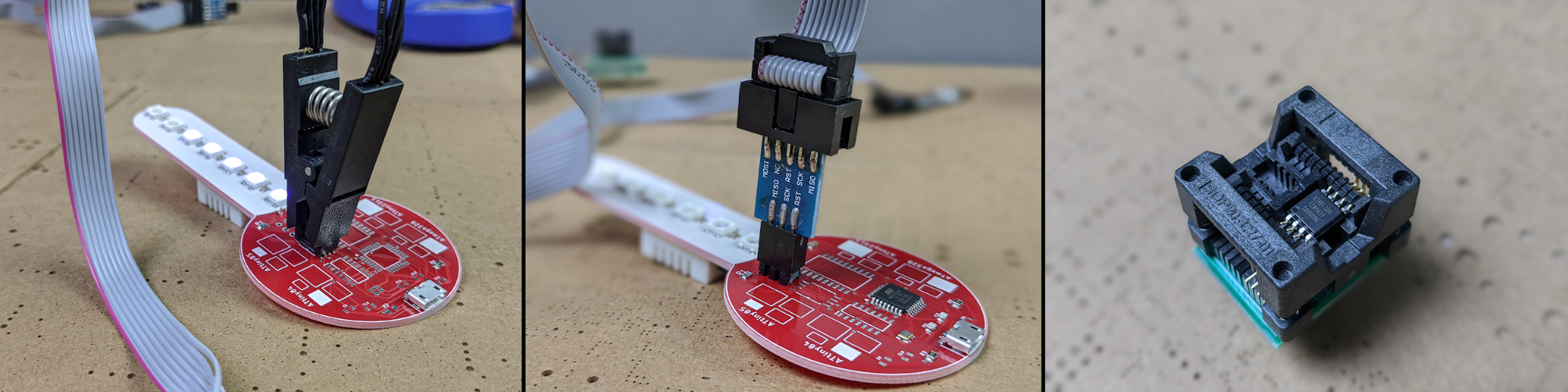
- Using an IC test clip along with an ISP programmer for in-situ programming,
- Incorporating PCB headers or test points for interfacing an ISP programmer with a PCB using a header or pogo pins,
- Direct programming using an SMT test clip or getting chips factory-programmed before soldering the microcontrollers to a board.
Meet the Custom Test PCB
In order to test various methods of programming ATtiny series microcontrollers, I designed a simple test PCB.
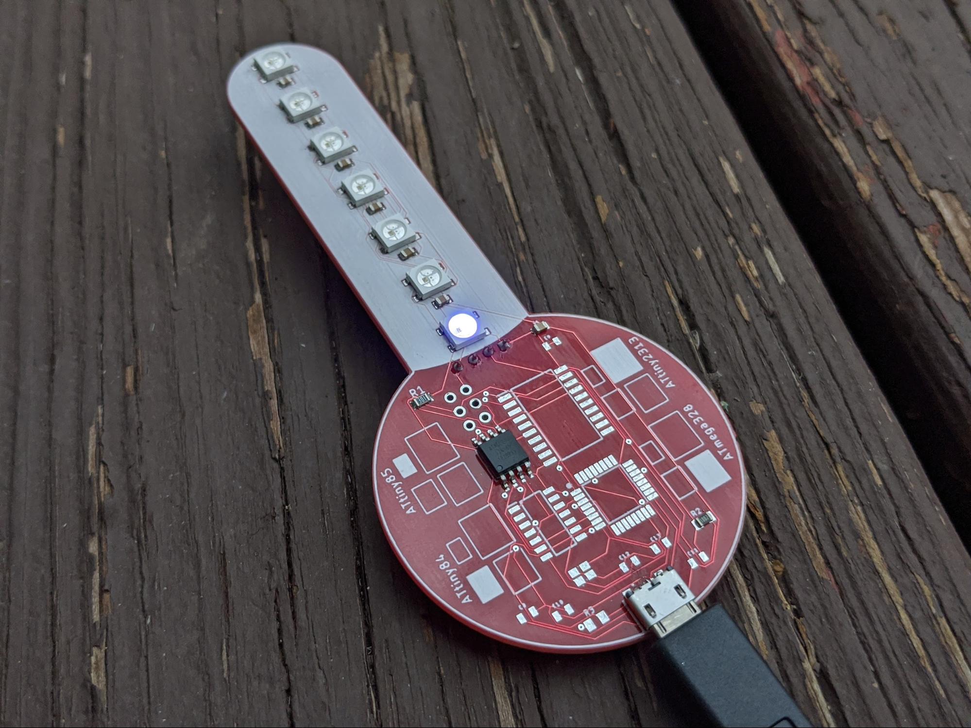
The PCB is a thermometer with a DHT22 temperature-humidity sensor on the backside. This sensor takes a reading of, in this case, just the temperature.
The back view of the custom PCB with a DHT22 sensor attached.
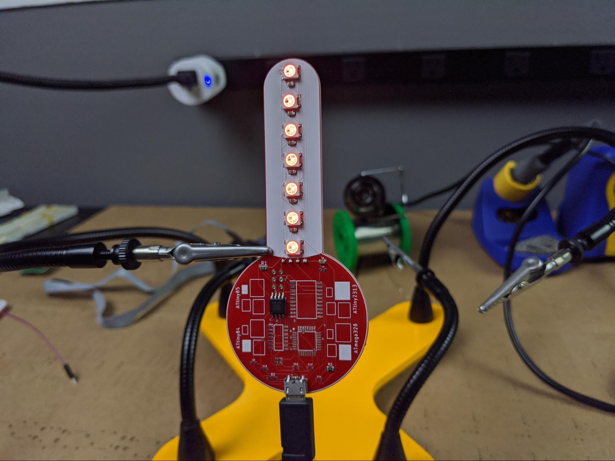
The test board also features a line of LEDs on the front, like the tube of mercury/alcohol on an analog thermometer. More LEDs light up at higher temperatures and, additionally, the LEDs change color from blue to red between low and high colors.
At cold temperatures, like outside in the winter, the LEDs glow blue and fewer will illuminate.
At high temperatures, like in front of a heat gun, the LEDs illuminate red and more of them turn on.
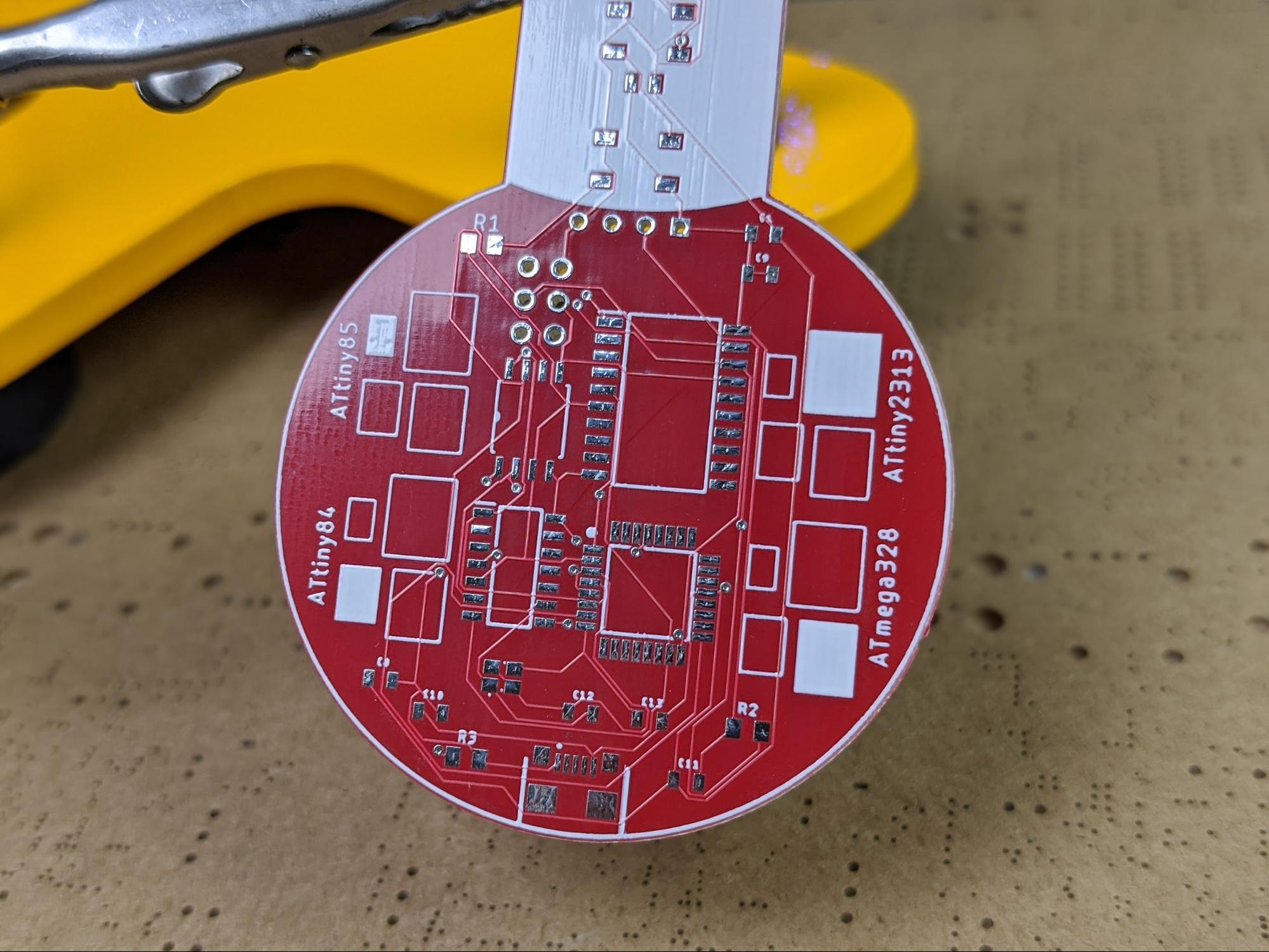
The main part of the test board has footprints for installing one of the ATtiny series microcontrollers: ATtiny84, ATtiny85, ATtiny2313, ATmega328. Each microcontroller also has a few passive components to make everything work.
The PCB also contains footprints for installing an ATtiny 84, ATtiny 85, ATtiny2313, or an ATmega328.
Lastly, the system is powered from a micro USB port on the bottom of the board.
If you want to build your own thermometer test boards, you can download the Autodesk Eagle design files here:
Eagle Files
I had my PCBs manufactured by SeeedStudio Fusion PCB in red, to match the color of alcohol thermometers. Aside from the DHT22, all the other components are SMD parts so the board can be assembled via reflow soldering.
Code to Run the Test PCB
The code to run the test PCB is not too complex.
At the start of every loop, the microcontroller takes a temperature reading from the DHT22. Then, two different map() statements are used to translate the temperature reading to (1) a color for the LEDs and (2) a number of LEDs to illuminate.
/*
   Project:  ATtiny Microcontroller Test Platform
   Published on Maker Pro
   Author:  Scott Hatfield (Toglefritz)
*/

// CONFIGURATION  //

// If you are using an ATint84, the LEDs are connected to pin 2. For any of the other
// microcontrollers, the LEDs are connected to pin 4.

// ATtiny84
// #define PIN 2

// ATtiny85 or ATTiny2313 or ATmega328
#define PIN 4

// NEOPIXEL SETUP //

// Include the Adafruit NeoPixel library
#include <Adafruit_NeoPixel.h>

#define NUMPIXELS 7   // There are seven LEDs on the board

// Set up the NeoPixel library
Adafruit_NeoPixel pixels(NUMPIXELS, PIN, NEO_GRB + NEO_KHZ800);

// DHT22 SETUP  //
#include "TinyDHT.h"

// The temperature sensor is connected to pin 3 for all microcontrollers
#define DHTPIN 3

#define DHTTYPE DHT22   // DHT 22  (AM2302)
DHT dht(DHTPIN, DHTTYPE); //// Initialize DHT sensor

// SKETCH VARIABLES  //
float temp;  // Stores temperature value
int color;   // The color of the LEDs, for use with the Wheel() function
int number;  // The number of LEDs to illuminate


void setup() {
  // Set up the LEDs
  pixels.begin();   // Initialize NeoPixel object
  pixels.clear();   // Set all pixel colors to 'off' to start
  pixels.setBrightness(50);   // The LEDs do not need to be super bright

  dht.begin();    // Initialize the DHT22 object
}

void loop() {
  // Read the temperature
  int16_t temp = 30;//dht.readTemperature();
  // Reading temperature or humidity takes about 250 milliseconds!
  delay(250);
  /*
     The DHT22 is capable of measuring temperatures between -40C and 125C. But, because this is supposed to
     be hand-held device, we will map the temperatures only to between -25C and  40C.
  */

  // Map the temperature reading to a color number used for the LEDs. At the coldest temperatures, the light will be blue,
  // at the hottest, the light will be red.
  color = map(temp, -18, 30, 75, 1);

  // Then, map the temperature reading to a number of LEDs to illuminate. At the lowest temperatures, only the bottom LED will
  // illuminate, at the hightest temperatures, all LEDs will illuminate.
  number = map(temp, -18, 30, 0, 6);

  // Set the LEDs to the color corresponding to the current temperature reading
  for(int i = 0; i <= number; i++) {
    pixels.setPixelColor(i, Wheel(color));
  }
  pixels.show();
}

// Wheel() is a helper function to get colors from single values between 0 and 255
// Input a value 0 to 255 to get a color value.
// The colours are a transition r - g - b - back to r.
// For a visual representation of the values, see https://docs.google.com/spreadsheets/d/1vYsRDL4QzcZtP30jqQByM2pK3_Xq2RPOyVwkcxQOnPI/edit?usp=sharing
uint32_t Wheel(byte WheelPos) {
    if(WheelPos < 85) {
        return pixels.Color(255 - WheelPos * 3, 0, WheelPos * 3);
    }
    else if(WheelPos < 170) {
        WheelPos -= 85;
        return pixels.Color(0, WheelPos * 3, 255 - WheelPos * 3);
    }
    else {
        WheelPos -= 170;
        return pixels.Color(WheelPos * 3, 255 - WheelPos * 3, 0);
    }
}
Trying ATtiny Programming Methods Using the Test PCB
As previously mentioned, there are three major methods for programming ATtiny series microcontrollers that we will explore in the next several sections of this series. Again, they are:
- Using an IC test clip to program individual microcontrollers
- Using ISP headers to allow microcontrollers to be programmed as part of the assembly process
- Using pre-programmed microcontrollers for high-volume production
In order to facilitate trying out these various programming methods, I designed the simple test PCB I've outlined here.
The PCB is a thermometer featuring a DHT22 temperature sensor along with a row of LEDs used to indicate the current temperature based on color and the number of illuminated LEDs. The subsequent parts of this series will all use this same test board to illustrate how to use the aforementioned programming methods.